01/19/2021 13,585 GAZ Gazelle
Author: Ivan Baranov
The purpose of power steering is to provide more convenient steering wheel control. Today, the power steering system is installed on Gazelle and many modern cars. You can learn more about the device, malfunctions and repair of the unit at home from this material.
[Hide]
Blog about UAZ
On Gazelle GAZ-3302 and GAZ-2705 vehicles, a steering system is installed, consisting of a steering column with a steering wheel, a steering mechanism and a steering drive. Some Gazelle GAZ-3302 and GAZ-2705 vehicles can be equipped with a steering mechanism with power steering.
Steering device for Gazelle GAZ-3302 and GAZ-2705, steering mechanism, steering column and steering linkage, design features.
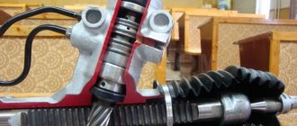
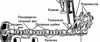
On Gazelle GAZ-3302 and GAZ-2705 cars, a steering mechanism of the screw-ball nut-toothed sector type is installed. The mechanism housing is cast from aluminum alloy. The gear sector is made integral with the bipod shaft.
The sector shaft is supported by two tapered roller bearings. To prevent rotation, the outer rings of the bearings are cored into the crankcase holes, closed with plastic plugs. A bipod is secured to the splined end of the sector shaft with a nut. The sector shaft engages with the ball nut. The ball nut has a screw groove inside and through the balls located in it, which act as threads, interacts with the steering mechanism screw.
Steering components and parts for Gazelle GAZ-3302 and GAZ-2705.
The inlet and outlet ends of the helical groove on the nut are closed between each other by a groove filled with the same balls as in the nut groove. When the screw is turned, the nut moves along its axis, and the balls, rolling along the grooves, enter one end of the groove. Then, moving inside, they come out of its other end and enter the screw channel on the other side of the nut, formed by the grooves on the screw and nut.
On the side surface of the ball nut there are cut rack teeth that engage with the teeth of the bipod sector shaft. Therefore, movements of the nut cause rotation of the bipod shaft, mounted on two roller bearings.
The ball nut screw is supported by two ball bearings. Their outer rings are pressed into the crankcase and top cover. The preload of the bearings is adjusted by shims installed under the top cover. The mechanism is sealed with rubber sealing rings and an oil seal.
Features of adjustment and lubrication of the steering mechanism on the Gazelle GAZ-3302 and GAZ-2705.
The screw with a ball nut and a set of balls are matched to each other and, if necessary, can only be replaced as an assembly. The engagement of the ball nut with the sector shaft is adjusted by turning the eccentric races of the sector shaft bearings. The steering mechanism is lubricated with transmission oil (0.5 liters), poured into the crankcase through a plug with a conical thread.
Steering column and steering wheel for Gazelle GAZ-3302 and GAZ-2705, design features.
The steering column is injury-proof. With the ability to adjust its position in height and tilt. The steering column shaft, mounted in a pipe on two bearings, transmits torque to the steering mechanism through an intermediate cardan shaft. The steering column is equipped with an anti-theft device. The steering wheel is mounted on the splines of the steering column shaft and secured with a nut.
Steering device with power steering for Gazelle GAZ-3302 and GAZ-2705.
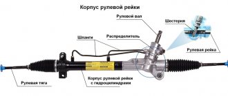
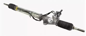
Some Gazelle GAZ-3302 and GAZ-2705 vehicles can be equipped with power steering steering ShNKF 453461.120. In contrast to steering with a conventional screw-ball nut type mechanism, it contains an integral steering mechanism, a power steering pump, a reservoir for working fluid and connecting hoses - suction, discharge and drain.
The steering gear ratio is 17.3. The integral steering mechanism is mounted on the left frame side member in the same manner as a conventional steering mechanism. It is a two-stage mechanical gearbox with a screw-ball nut-toothed rack-three-tooth sector transmission, with a built-in power cylinder and distributor.
The steering gear housing is also a power cylinder in which a piston nut moves, the design is almost similar to the ball nut of a steering mechanism without power steering, but has an outer ring seal.
A rotary-tangential type distributor is built directly into the housing of the integral steering mechanism, which controls the flow of working fluid. It provides a tracking effect of the amplifier depending on the angle of rotation of the steering wheel.
The piston nut divides the power cylinder into two cavities, the pressure in which is the same when the steering wheel is stationary. When the steering wheel is turned in one direction or another, the distributor connects the corresponding cavity of the cylinder with the supply line, and the other with the discharge line.
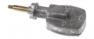
Power steering pump for Gazelle GAZ-3302 and GAZ-2705.
The power steering pump is vane type, double acting. Installed in front of the engine on a fixed bracket. It is driven by a six-ribbed poly-V belt common to mounted units. Belt tension is adjusted by moving the tension roller. For the ZMZ-40524 engine, belt tension is ensured by an automatic tensioner.
Parts of the power steering pump for Gazelle GAZ-3302 and GAZ-2705.
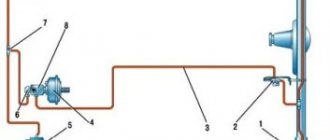
Power steering hydraulic system reservoir for Gazelle GAZ-3302 and GAZ-2705.
The power steering hydraulic system reservoir, installed on the left mudguard of the engine compartment, serves as a reservoir for working fluid and ensures normal temperature conditions in the hydraulic system, compensation for possible leaks of working fluid during operation and its cleaning from wear products.
A non-separable plastic tank YaMZ.993.001 is installed on the Gazelle GAZ-3302 and GAZ-2705 cars. When the filter element becomes clogged, it is replaced as an assembly. The tank is equipped with a cardboard filter element that provides particle filtration fineness of no more than 45 microns.
Depending on the design of the tank, there may be no dipstick in the tank plug. Instead, to determine the liquid level, “MAX” and “MIN” marks are applied to the wall of the tank. The system uses hydraulic fluid for automobiles, filled in a volume of 1.6 liters, as the working fluid.
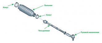
Steering linkage for Gazelle GAZ-3302 and GAZ-2705.
The steering linkage consists of:
— Longitudinal traction. — Cross rod adjustable in length. — Two swing arms mounted on the steering knuckles. — Steering rod joints.
The steering bipod is connected by a longitudinal rod to the steering knuckle lever of the left front wheel. The tie rod links the arms of both wheels, synchronizing their rotation. Its length can be adjusted, allowing you to change the toe angle of the wheels. The longitudinal and transverse inclination of the steering axis and the camber of the front wheels are specified by the design of the front suspension and are not adjustable during operation.
Steering angles and toe-in of the front wheels on Gazelle GAZ-3302 and GAZ-2705.
Non-adjustable suspension parameters for Gazelle GAZ-3302 and GAZ-2705. The lateral inclination angle of the steering axis and the camber of the wheel and the longitudinal inclination of the steering axis.
All hinges connecting the elements of the steering drive are unified, sealed, non-dismountable and non-adjustable. They are protected from dirt, dust and moisture by rubber seals.
source
Typical faults and solutions
Like any component, power steering can fail from time to time.
The main malfunctions and methods for eliminating them are given below:
- The system's drive belt is worn or poorly tensioned. In this case, the belt is either changed or its position is adjusted.
- The steering wheel does not turn well, this can be due to wear on the strap, a low oil level in the system, a reduced engine speed, or a clogged filter. In addition, the problem may be low pump pressure or an air lock in the lines. Depending on the problem, the solution may involve adding consumables, adjusting the idle speed, replacing the filter, or repairing the pump. It would be a good idea to check the tightness of the connections.
- There is a mechanical failure in the operation of the steering system; it needs to be diagnosed.
- If the pump does not work, you need to either repair it using a repair kit or change the seals.
- Wear of steering elements or violation of drive geometry. Failed parts should be replaced.
- If hydraulic fluid is escaping from the relief valve, you need to locate the leak and fix the problem. The reason may lie in the inoperability of the pump; its operating pressure should be checked.
- If the tires are damaged or worn out, it is necessary to identify the faulty elements and replace or repair them.
Is it possible to mix?
Mixing oils is acceptable, but must be done with great care. The main thing is to follow the manufacturer’s recommendations, which often indicate on the packaging which brands and classes can be mixed with
It is not recommended to make your own decision about mixing, for example, synthetics with mineral water, if the manufacturer does not give such recommendations. However, anything happens on the road, sometimes you have to fill in what you managed to find here and now. In this case, as soon as possible, it is recommended to completely drain the mixed fluids, replacing them with one used for this hydraulic system.
Repair instructions for power steering pump
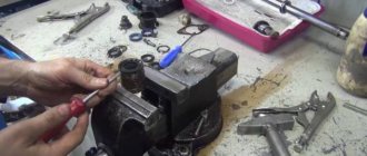
As you might have guessed from the previous paragraph, if the power steering on a Gazelle does not work, then this is due to the pump. To repair this element in a car with your own hands, you will need to purchase a repair kit in advance. You can buy it at any themed store. The main difficulty in repair is that the pump is not dismountable.
The repair procedure is carried out as follows:
- Remove the pump and disassemble it according to the instructions included in the kit.
- Clean the device from dirt; there may be signs of the cause of failure on the case. Usually the problem lies in the wear of the oil seal, then it will need to be replaced. When installing a new oil seal, the shaft must be modified.
- The oil seal can be installed in several ways. You can build a special recess on the outer part of the element, drill a corresponding threaded hole in the wall of the device, and then secure the oil seal with screws. You can also fix this part in the middle of the pump using specially curved ends of the housing.
- When the replacement of the element is completed, it will be necessary to reassemble the system in the reverse order. Please note that after the repair is completed, you may hear uncharacteristic noise when the power steering is operating. This is the grinding in of the new oil seal, so there is no need to worry about this. When the repair is completed, it is necessary to change the oil in the system.
Steering gearbox for Gazelle: diagnostics and repair
Today, the steering gear is installed on almost all modern models of Gazelle vehicles, regardless of the presence of power steering. The main function of the presented mechanism is considered to provide control of the machine, therefore the technical serviceability of the device directly affects the safety of the driver and passengers while driving.
Signs that repairs are needed
Gazelle steering gear repair
In any car, the steering parts are subject to the greatest degree of wear, since they bear heavy loads when driving on uneven roads, cornering, and sudden braking. Therefore, the Gazelle steering gear often fails, as a result of which it is urgently adjusted. The list of signs of malfunction of the unit in question usually includes:
- Vibration or knocking in the device transmitted through the steering wheel;
- Having difficulty turning the steering wheel;
- Presence of play in the gearbox;
- Oil leaks in the mechanism.
Sale of new SUVs
Credit 9.9%, installments 0%, discounts, gifts!
If one or several signs appear, immediate adjustment of the steering gear is required, which will allow timely elimination of malfunctions in the operation of the device and reduce the risk of failure of other components of the vehicle.
Gazelle steering gear
Work order
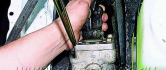
Professional steering adjustment on Gazelle models begins with its careful dismantling. Next, remove the top plastic cover from the mechanism along with the foam rubber seal and the head of the 13 key, and unscrew the four fastening bolts of the metal protection. We remove one of the adjusting shims located inside, assemble the device in the reverse order, check the play and, if there is any play, disassemble the unit back, removing another spacer ring.
When it has been possible to ensure that there is no backlash, it is necessary to adjust the gap when engaging the nut pair - shaft-sector. To perform this operation, you should install the bipod on the shaft and successively rotate the screw to move it to the middle position, and then turn the sector shaft directly behind the bipod. The play of the bipod tip should not be felt or exceed 0.3 mm.
When the mentioned indicator is greater, then using a plastic screwdriver we dismantle the plastic cover of the gearbox, after which we remove the two plugs. Using metal pliers, remove the spring rings on both sides of the body and straighten the holes on the edge of the outer ring. The eccentric outer rings are rotated clockwise until the gaps with the sector shaft are removed. To prevent the rings from turning, we fix them by bending the collars in the grooves of the crankcase. We assemble and install the mechanism in the reverse order.
Thus, adjusting the steering gear on a Gazelle car is an important repair measure that allows you to restore the functionality of vehicle control, significantly increasing the safety of passengers while driving.
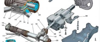
Steering without power steering
Steering without power steering:
- B – rib on the top cover;
- C – mark at the end of the screw;
- crankcase;
- screw with ball nut;
- shaft sector;
- filler plug;
- shims;
- screw;
- bolt;
- fork;
- lid;
- wedge;
- steering shaft seal;
- cardan shaft;
- sealing ring;
- retaining ring;
- outer ring of the sector shaft bearing;
- sector shaft seal;
- lid;
- bipod;
- side cover;
- cork.
The steering (Fig. 6.1 and 6.2) consists of an adjustable steering column with a shaft and wheel, a propeller shaft, a steering mechanism and a steering drive. The design of the steering column (Fig. 6.2) allows you to change the position of the steering wheel in height and angle.
The steering mechanism, consisting of a screw with a ball nut 2 (Fig. 6.1) and a sector shaft, is mounted in an aluminum crankcase, which is attached to the left frame side member using a special bracket. The steering gear ratio is 23.09 (in the middle part).
The screw with ball nut 2 is installed in the crankcase on two angular contact bearings, the outer races of which are installed in the crankcase and the upper cover of the steering mechanism, and the inner races are pressed onto the steering gear screw. The steering gear screw bearings are adjusted using shims 5 installed under the top cover of the steering gear.
As the screw rotates, the balls roll along the screw channel, causing the ball nut to move. The balls are manufactured with high precision and differ from each other by no more than 4 microns. The mechanism assembly, consisting of a screw, a ball nut and a set of balls, cannot be disassembled. High quality processing and precision selected parts ensure easy and smooth operation of the steering mechanism.
Steering wheel and column:
- driveshaft fork;
- wedge;
- nuts;
- thrust washer;
- top casing;
- ignition switch;
- lower casing;
- nuts;
- steering wheel;
- bolt;
- lever
With its teeth, the ball nut engages with the toothed sector of the bipod shaft 3. The bipod shaft rotates on two cylindrical roller bearings, the inner race of which is the shaft itself. The bipod shaft and steering gear cover are sealed with rubber rings. From axial movement, the outer races of the bipod shaft bearings are secured with retaining rings 14, and from rotation - by punching their races into the holes in the crankcase, closed by plugs 20. The steering mechanism screw is connected to the steering column shaft using a cardan shaft. The hinge forks are secured to the shafts with wedges 2 (Fig. 6.2.).
The steering column is attached with four bolts to the clutch and brake pedal bracket. The steering column shaft rotates on two ball bearings. There is no need to adjust the steering column shaft bearings during operation.
The steering wheel is mounted on the cone and splines of the steering shaft and is secured with a lock washer and nut.
Possible steering malfunctions and ways to eliminate them
| Cause of malfunction | Elimination method |
| Increased angle of free rotation of the steering wheel | |
| Increased clearance in the engagement of the nut-sector pair | Adjust the nut-sector engagement |
| The appearance of a gap in the propeller bearings | Adjust the propeller bearings |
| Excessive wear of steering rod joint parts and their fastenings | Replace worn parts |
| Increased play of wheel hubs | Adjust the clearance in the wheel hub bearings |
| Loosening the fork mounting wedges and the bipod mounting nut | Tighten loose nuts |
| Loosening of the steering mechanism to the bracket>7 and the bracket to the frame | Tighten the fastening |
| Sticking, squeaking, or clicking noises in the steering gear | |
| Excessive wear of the screw or shaft - chipping or dents on their surface | Replace the screw nut or sector shaft |
| Weak fixation of the steering column | |
| Column locking mechanism is loose | Adjust the column locking mechanism |
| Steering column play | |
| Axial movement of the steering wheel shaft relative to the housings | Replace worn steering column shaft bearing bushings |
| Increased steering effort (“heavy steering wheel”) | |
| Seizure of pin bushings | Replace bushings and kingpin |
| Rotating the king pin bushings in the knuckle bosses | Replace bushings and kingpin |
| Contamination of the kingpin support bearing (when turning the wheels, a creaking sound is heard in the support bearing) | Wash the support bearing through a grease nipple with a mixture of 50% kerosene and 50% gear oil. Lubricate the support bearing through a grease nipple until grease appears from under the seal. |
| Lubricant leak | |
| Wear or loss of elasticity of the oil seal and steering gear seals | Replace worn oil seal and rubber sealing rings |
Design and procedure for dismantling the control unit of a Gazelle car
Composition of the Gazelle control unit:
- A wheel mounted on a shaft and located inside a column that can be adjusted in height and tilt.
- Rotation mechanism.
- Drive unit.
Repair of the Gazelle steering wheel is carried out as needed, mainly when the first signs of a malfunction appear.
GAZ steering device
The gearbox mechanism is compact and quite simple. The work does not require high qualifications, but it should not be the first step in setting up.
The fact is that in order to remove the problem node, you will need:
- Loosen the front wheel mounts
- Raise the front axle and place a support.
- Knock out the traction.
- Remove the gearbox along with the bipod.
Gazelle steering mechanism
Since these actions are quite difficult, the process of adjusting the steering gear must begin after some preparatory operations:
- Checking the rod ends.
- Wheel alignment adjustment.
- Adjusting the position of the column and driver's seat.