20 Jun 2015 | | no comments
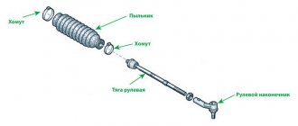
The steering of the VAZ 2115-14 car is injury-proof, with an adjustable steering column angle, with a rack and pinion steering mechanism, with two rods having rubber-metal joints on the side of the steering mechanism and ball joints on the side of the swing arms.
Fig.1 Steering
1-rod joint, 2-swing arm, 3-rod end, 4-lock nut, 5-rod, 6 and 11-inner tie rod ends, 7-ball joint pin, 8-protective cap, 9-inlay ball pin, 10-bolts securing the tie rods to the rack, 12-steering gear mounting bracket, 13-steering gear support, 14-connecting plate, 15-protective cover, 16-locking plate, 17-steering gear housing, 18-pin bolt , 19-connecting elastic coupling, 20-rack, 21-rack support bushing, 22-damping ring, 23-rubber-metal hinge, 24-facing casing (upper part), 25-steering wheel, 26-steering column adjustment lever, 27 -steering shaft mounting bracket, 28-cladding casing (lower part), 29-steering intermediate shaft, 30-protective cap, A-surface of the ball joint housing, B-surface of the swing arm
The steering of the car is attached to the front panel of the body with two brackets 12 on rubber supports 13. In the steering gear housing 17, a drive gear is installed on roller and ball bearings, which meshes with the rack 20. The rack is pressed to the gear by a spring through a metal-ceramic stop, which is sealed in crankcase with a rubber ring. The spring rests against a nut with a locking ring, which creates resistance to unscrewing the nut.
The ball bearing of the gear is pressed by a nut with an o-ring. The nut is locked in the crankcase with a washer and covered with a boot mounted on the drive gear shaft. There are marks on the steering gear housing and boot for correct assembly of the steering gear.
A protective cap 30 is put on the steering gear housing on the left side, and a pipe with a longitudinal groove is pressed on the right side. The spacer bushings of the rubber-metal hinges of the inner tips 6 and 11 of the steering rods pass through the groove of the pipe and the holes of the protective cover 15. The steering rods are attached to the rack with bolts 10, which pass through the connecting plate 14 and the spacer bushings of the rubber-metal hinges 23. The bolts are secured with a locking plate 16.
The steering drive consists of two steering rods and swing arms and 2 telescopic front suspension struts. Each steering rod consists of an inner tip 6 or 11, a tip 3 and a tubular rod 5. The length of each rod is changed by a tubular rod 5, which is screwed onto the rod ends and secured with nuts 4. The head of the outer tip contains the ball joint parts: liner 9, pin 7 and liner spring. Swivel arms 2 are welded to the front suspension struts.
Fig.2 Steering column assembly
1-lower flange of the elastic coupling, 2-elastic coupling, 3-intermediate steering shaft, 4-steering shaft mounting bracket, 5-upper steering shaft, 6-extension spring, 7-facing casing (lower part), 8- retaining ring, 9-steering column position adjustment lever, 10-lever adjustment sleeve, 11-spacer sleeve, 12-pinch bolt, 13-steering shaft bracket pipe, 14-contact plate holder, 15-steering wheel mounting nut, 16- steering wheel, 17-facing casing (upper part), 18-steering shaft bearing, 19-support plate bushing, 20-spacer bushing, 21-universal joint crosspiece, C and E-windows for adjusting the position of the steering column.
- We repair the Kalina
The steering shaft consists of an upper shaft 5 and an intermediate shaft 3. The upper and intermediate shafts are connected to each other by a cardan joint with a cross 21. The intermediate shaft 3 is attached to the steering gear drive gear through an elastic coupling 2 with a lower flange 1. The steering wheel is attached to the upper shaft 5 16 with nut 15. The upper shaft is located on bearings 18 in pipe 13. Bracket 4 for fastening the steering shaft is secured in four places to the body bracket, with the front part of the bracket secured with two bolts, and the rear part of the bracket with nuts.
Bracket 4 and pipe 13 are hingedly connected to each other by two plates using four bolts located in plastic bushings 19 and spacer bushings 20. With this connection, pipe 13 and shaft 5 relative to bracket 4 have angular and axial movements, which are limited by windows “C” and "E". To fix the pipe 13 relative to the bracket 4, there is a lever 9.
The hub of the lever 9 has splines with which it is connected to the adjusting sleeve 10. The sleeve 10 is located on the coupling bolt 12, which passes through the slots of the guide plates of the pipe 13 and bracket 4 (through windows “C” and “E”). When lever 9 is turned down, the fixation of pipe 13 in bracket 4 is loosened, which allows you to manually change the angle of the steering column.
Other articles in the category “VAZ 2115 - 14”:
- Removing and installing the gearbox of a VAZ car...
- The front wheel drive of the VAZ 2115 is ...
- Gearbox of a VAZ 2115 - 14
- Clutch of a VAZ 2115 - 14 car
- Crankshaft of VAZ 2111 engine
- VAZ 2111 engine assembly
- Disassembling the VAZ 2111 engine
- Repair of the cylinder head of the VAZ 2111 engine
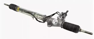
Steering with rack and pinion steering mechanism and damping element on the steering wheel.
Rice. 5.1. Steering: 1 – tie rod end; 2 – ball joint of the tip; 3 – rotary lever; 4 – lock nut; 5 – traction; 6.8 – inner tie rod ends; 7 – bolts securing the steering rods to the rack; 9 – steering gear mounting bracket; 10 – steering gear support; 11 – protective cover; 12 – connecting plate; 13 – locking plate; 14 – rubber-metal hinge; 15 – damping ring; 16 – rack support sleeve; 17 – rack; 18 – steering gear housing; 19 – coupling coupling bolt; 20 – lower flange of the elastic coupling; 21 – upper part of the facing casing; 22 – damper; 23 – steering wheel; 24 – ball bearing; 25 – steering shaft; 26 – lower part of the facing casing; 27 – steering shaft mounting bracket; 28 – protective cap; 29 – roller bearing; 30 – drive gear; 31 – ball bearing; 32 – retaining ring; 33 – protective washer; 34 – sealing ring; 35 – bearing nut; 36 – boot; 37 – sealing ring of the stop; 38 – retaining ring of the stop nut; 39 – rack stop; 40 – spring; 41 – stop nut; 42 – ball joint pin; 43 – protective cap; 44 – ball pin insert; A – mark on the boot; B – mark on the steering gear housing; C – surface of the ball joint; D – surface of the swing arm
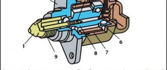
In the housing 18 (Fig. 5.1) of the steering mechanism, on roller bearings 29 and ball bearings 31, a drive gear 30 is installed, which meshes with rack 17. The rack is pressed against the gear by spring 40 through a metal-ceramic stop 39, which is sealed in the crankcase with a rubber ring 37. Spring rests against the nut 41 with a locking ring 38, which creates resistance to unscrewing the nut.
The ball bearing of the gear is pressed by a nut 35 with an o-ring 34. The nut is locked in the crankcase with a washer and closed by a boot 36 mounted on the drive gear shaft.
There are marks A and B on the steering gear housing and boot for correct assembly of the steering gear.
A protective cap 28 is put on the steering gear housing on the left side, and a pipe with a longitudinal groove is pressed on the right side. The spacer bushings of the rubber-metal hinges of the inner tips 6 and 8 of the steering rods pass through the groove of the pipe and the holes of the protective cover 11. The steering rods are attached to the rack with bolts 7, which pass through the connecting plate 12 and the spacer bushings of the rubber-metal hinges 14. The bolts are secured with a locking plate 13.
- VAZ 2114: replacing the steering rack - signs of failure, choosing a new part
The steering shaft 25 is connected to the drive gear 30 by the lower flange 20 of the elastic coupling. The upper part of the shaft rests on a radial ball bearing 24. At the upper end of the shaft, a steering wheel 23 with a damper 22 assembly is secured with a nut on the splines.
The steering drive consists of two horizontal rods 6 and 8 and rotary arms 3 telescopic struts of the front suspension. The length of each rod is changed by a tubular rod 5, which is screwed onto the end of the rod and secured with nuts 4. In the head of the outer tip there are parts of the ball joint: liner 44, pin 42 and liner spring. The steering arms are welded to the front suspension struts.
The steering is rack-and-pinion type, with a propeller shaft and a tilt-adjustable steering column.
The steering wheel is mounted on the splines of the steering shaft and secured with a self-locking nut.
The steering shaft is composite, consisting of an upper and intermediate shaft connected by a universal joint. The upper shaft rotates in two bearings pressed into the steering column tube. An ignition switch with an anti-theft device is installed on the top of the column pipe.
The steering column bracket is attached to the body with two bolts and two nuts. The bolts are special, with break-off heads. When these bolts are tightened, their heads break off.
Steering:
1 - sealing ring; 2 — protective cover for the tie rod end; 3 - spring ring; 4 — ball pin; 5 — tie rod end; 6 — rod coupling with locknuts; 7 — steering rod; 8, 10 — steering gear mounting brackets; 9 — steering rod; 11 — right steering gear support; 12 — protective cover of the steering mechanism; 13 — steering mechanism; 14 - seal; 15 — protective cap; 16 — coupling bolt of the elastic coupling flange; 17 — coupling bolt of the steering column fixing mechanism; 18 — spacer sleeve; 19 — universal joint; 20 — upper steering shaft; 21 — steering wheel; 22 — steering wheel fastening nut; 23 — steering wheel pad; 24 — decorative insert of the lining; 25, 33 — steering shaft bearings; 26 — bracket for fastening the steering column to the body; 27 — retaining ring; 28 — steering column fixation lever; 29 — adjusting sleeve; 30 — washers; 31 — fixing plate; 32 — bolt with a tear-off head; 34 — intermediate steering shaft; 35 — rubber elastic coupling; 36 — left steering gear support
The bracket is pivotally connected to the steering column tube and is equipped with a steering column fixation mechanism. By moving the locking lever to the lower position, you can change the angle of the steering column. When the lever is raised, the column is fixed in the selected position.
The steering shaft is connected to the steering mechanism through a rubber elastic coupling.
- Steering VAZ 2106: Malfunctions, Tuning
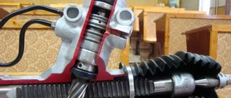
The steering mechanism consists of a crankcase, a drive gear and a rack in gearing. The mechanism is secured to the partition of the engine compartment with two brackets on rubber supports. When the steering wheel is turned, rotation is transmitted through the upper and intermediate shafts of the steering column to the drive gear, which, when turning, moves the rack.
Symptoms of malfunction
- Knock on rough roads . When hitting bumps, you will hear dull or ringing metallic sounds from the front of the car. This does not always happen due to wear on the steering rack; sounds can also arise from other components: ball joint, tip, wheel bearing.
- Large steering play. As the mechanism wears out, the gaps between the teeth increase, causing free play to increase. Play can also appear when the steering tips and ball joints are worn out.
Backlash should definitely be eliminated at the initial stages of its appearance, since delaying repairs can lead to complete failure and the replacement of the element.
- Steering wheel jamming . Most likely the cause of the problem will be the steering rack. Most often this occurs due to damage to the anthers. Water and dirt begin to enter the mechanism body. The lubricant washes out or thickens, causing the teeth to cling to each other unevenly.
A similar problem also occurs when the element is incorrectly adjusted.
Signs of a faulty steering rack
Any knocking or noise coming from the chassis of the car should not be ignored. The failure of one suspension element over time affects other components of the machine, which increases the risk of getting into an accident during operation. The rack and pinion steering mechanism itself is quite simple, but when driving on bumpy roads, its wear increases significantly. Despite the fact that production of the 2114 model was discontinued about 8 years ago, stores still have all the spare parts for the car, including the rack and pinion mechanism. It is not difficult to accurately determine the breakdown of this chassis element. Look out for the following signs:
- A metallic knock that occurs when driving over uneven surfaces is a clear sign of wear on the mechanism. In addition to this mechanism, similar sounds can be produced by worn ball joints and wheel bearings, so you should listen carefully to the source of the knock;
- Increased free play of the steering wheel (play). From the factory, the 2114 model already has a small amount of play, but if the rack is faulty, the free play can increase significantly, which will complicate movement when turning at high speeds and changing lanes;
- Wedging or lack of smoothness when turning the steering wheel. This sign most likely indicates a malfunction. Wear is often caused by rupture of anthers and dirt entering the structure.
Delaying the repair of a faulty unit leads to an even greater deterioration in the process of steering a car. Corrosion, dirt, jamming - at one moment they can cause the steering wheel to jam, which can lead to tragedy when driving.
Important! Timely replacement of the steering rack boot will help avoid the ingress of dirt, moisture and further corrosion.
Replacing the steering rack on a VAZ 2114 yourself is possible in a garage where there is a pit or a lift. To carry out replacement work with a new spare part, it is enough to acquire tools and instructions, which can be found below.
Required Tools
To service the mechanism we need the following set of tools:
- Open-end wrenches. It would be good if there was a complete set, but usually the sizes required are: 8, 10, 13, 22.
- Set of heads;
- Flat and Phillips screwdrivers;
- Pliers or round nose pliers;
- Hexagon 17 (better set);
- Jack and wheel wrench;
- Chisel and hammer;
- It would be great to have a special puller for tie rods;
- WD-40 or Liquid Wrench for thread processing.
- Special key for adjusting the rack
Also, for safety, it is necessary to prepare supports for the wheels of the car.
Steering rack repair kit for VAZ 2114
When starting to overhaul the mechanism, you need to consider the market for repair kits. There are several types:
- The first consists only of rubber bands, gaskets and dampers. It is suitable for changing the lubricant inside the mechanism and for light maintenance. The price for a set is about 200 rubles.
- The second is complemented by two bearings, which is also suitable for easy maintenance of the mechanism. The cost of the set is about 500 rubles.
- The latest repair kit has almost all internal mechanisms and implies a complete replacement of units. The price is about 2000 rubles.
Before purchasing a kit, check which rack is installed on your car and write down its number. This will help you avoid making mistakes when purchasing.
Removing the steering rack
When starting to repair the VAZ 2114 steering rack, first of all we need to remove it. We do this using the following technology:
- We park the car on a level surface. For safety, we put supports under the wheels to prevent them from rolling back.
- Raise the car with a jack, loosen the wheel nuts and remove it. Similar work needs to be done on the other side.
- There is a hole in the arch on the right side that is closed with a plug. Let's take it off.
- When the absorber is installed, it is necessary to loosen the clamp and, without disconnecting the hoses, move it to the side.
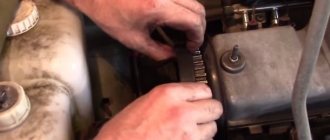
- Using a hammer and chisel, we bend the antennae onto the plates that hold the tie rod nuts.
- We unscrew the bolts and pull them out along with the plate. We move the pulls to the side.
- We find the junction of the column shaft with the gear shaft of the mechanism. It is located at the front panel from the passenger compartment. Let's separate them.
- Using a socket or a 13mm wrench, unscrew the brackets that hold the steering rack. They often become very rusty and unscrewing them becomes problematic, so it is advisable to first treat them with WD-40 and wait a few minutes.
- We move the mechanism towards the engine to free the shaft and remove it.
- We pull it out through the hole described in the third paragraph.
After this, the dismantling is completed and you can begin to repair or replace the mechanism.
How to remove the steering wheel?
Dismantling the steering wheel on VAZ 2114 and 2115 is carried out using the same method. However, remember that according to the Code of Administrative Offenses, replacing a steering wheel with a steering wheel different from the original is considered illegal modification of the steering structure and vehicle control system. Such tuning falls under Part 2 of Article 12.5 of the Code of Administrative Offenses on driving a vehicle in the presence of malfunctions or conditions under which its operation is prohibited. Recently, traffic police officers have been quite zealous in catching violators of this article, so think carefully before embarking on the replacement process.
The standard VAZ 2114 steering wheel looks unattractive, so someone may want to replace it
Required Tools
To remove and then install a new steering wheel, you will need the following tools:
- new steering wheel (make sure the part you choose fits your car);
- set of screwdrivers with straight and Phillips slots;
- 24 mm socket head;
- pencil or marker;
- hammer (in some cases);
- a soft metal drift (included with the hammer);
- wire cores (in some cases).
Please note that after completing all the work, you will have to remove traces of a pencil or marker from the steering wheel cover and front panel. To avoid problems with subsequent cleaning, consider the coating material of these interior elements. You should not use permanent, or as they are also called, indelible markers, especially if the parts are covered with high-quality natural leather of a light shade. The easiest way to remove marker is water-based. But it is better to use a regular pencil: it can be erased with a regular eraser.
Steering wheel removal process
There is a signal inside the steering wheel that receives power from the battery, so the first thing you need to do is turn off the power to the car. To do this, you just need to disconnect the negative terminal. After this, you can safely begin the dismantling process.
- Remove the ignition key from the lock.
- Turn the steering wheel so that the system locking the steering shaft is activated. Your steering wheel is now locked in a straight position.
- In order to subsequently correctly install the new part while maintaining control accuracy, apply a mark to the steering wheel with a pencil. Place a similar mark on the dashboard right next to it.
- Using a straight screwdriver, pry the cover with the Lada inscription on the steering wheel and remove it. This element is attached using ordinary plastic clips, so removing it is not difficult. However, due to the thin plastic, the part breaks easily. If you plan to continue using your old steering wheel, be careful.
- Under the trim you will see two screws. They hold the steering wheel cover. Unscrew them using a Phillips screwdriver and then remove the cover.
- In the central part of the structure you will see a large nut. It should be unscrewed using a 24 mm socket.
- The steering wheel no longer holds anything. To remove it, grab the steering wheel with both hands and pull each side in turn. There's no point in trying. If the part has not been dismantled before, it will be quite difficult to move. Do not try to remove the part with one jerk: you may accidentally injure yourself.
- If attempts to remove the steering wheel using the method described in point 7 are unsuccessful, use a small hammer and drift. In addition to additional tools, you will need an assistant. One person from the pair should pull the steering wheel, and the second should hit the drift attached to the end of the steering shaft with a hammer.
Removing the steering wheel for VAZ 2114 and VAZ 2115
First of all, you need to remove the cover
The screws under the trim should be unscrewed
using a 24mm socket you need to unscrew the central screw
If you cannot remove the steering wheel by hand, use a hammer
Experts recommend not turning off the central nut completely, as it can protect you from serious injury in the event of a sudden break of the steering wheel. Make several turns while performing step 6, and when the part comes off the steering shaft, unscrew it completely by hand.
Video: how to remove the steering wheel on VAZ 2114 and 2115 cars
In this simple way you can dismantle the steering wheel on a VAZ 2114 and VAZ 2115.
Disassembly
If you decide to carry out maintenance yourself, then you should disassemble it in order:
- We cut off or bite through the plastic clamps that are located on the sides of the protective casing. We remove it and inspect it for breaks or cracks.
- The side protective caps are also attached to the clamps. We carry out a similar procedure and remove them.
- Unscrew the adjusting screw with a 17 octagonal wrench.
- Then we take out the sealing and retaining ring, the spring and the stop. We check the emphasis for scuffs and other damage, since its condition directly affects its performance.
- Now we need to remove the steering gear boot. It sits tightly on the body and does not have any special fastenings.
- We take out the lock washer and unscrew the bearing nut. Then remove the o-rings. After the steering shaft.
- We check the condition of the bearing. In case of wear, we knock it down using an extension or a gentle blow with a hammer. We press in the new bearing using a yew or a press.
- Then we check the condition of the needle bearing. We take it out with a screwdriver, carefully lifting it up.
- We take the rail itself out of the body. We clean off the old grease and inspect the condition.
- The last step is to remove the bushing. To do this, use a screwdriver to move it from its seat and after that it can be easily removed.
Steering column VAZ 2114 device
The steering is rack-and-pinion type, with a propeller shaft and a tilt-adjustable steering column.
The steering wheel is mounted on the splines of the steering shaft and secured with a self-locking nut.
The steering shaft is composite, consisting of an upper and intermediate shaft connected by a universal joint. The upper shaft rotates in two bearings pressed into the steering column tube. An ignition switch with an anti-theft device is installed on the top of the column pipe.
The steering column bracket is attached to the body with two bolts and two nuts. The bolts are special, with break-off heads. When these bolts are tightened, their heads break off.
Steering:
1 - sealing ring; 2 — protective cover for the tie rod end; 3 - spring ring; 4 — ball pin; 5 — tie rod end; 6 — rod coupling with locknuts; 7 — steering rod; 8, 10 — steering gear mounting brackets; 9 — steering rod; 11 — right steering gear support; 12 — protective cover of the steering mechanism; 13 — steering mechanism; 14 - seal; 15 — protective cap; 16 — coupling bolt of the elastic coupling flange; 17 — coupling bolt of the steering column fixing mechanism; 18 — spacer sleeve; 19 — universal joint; 20 — upper steering shaft; 21 — steering wheel; 22 — steering wheel fastening nut; 23 — steering wheel pad; 24 — decorative insert of the lining; 25, 33 — steering shaft bearings; 26 — bracket for fastening the steering column to the body; 27 — retaining ring; 28 — steering column fixation lever; 29 — adjusting sleeve; 30 — washers; 31 — fixing plate; 32 — bolt with a tear-off head; 34 — intermediate steering shaft; 35 — rubber elastic coupling; 36 — left steering gear support
The bracket is pivotally connected to the steering column tube and is equipped with a steering column fixation mechanism. By moving the locking lever to the lower position, you can change the angle of the steering column. When the lever is raised, the column is fixed in the selected position.
The steering shaft is connected to the steering mechanism through a rubber elastic coupling.
The steering mechanism consists of a crankcase, a drive gear and a rack in gearing. The mechanism is secured to the partition of the engine compartment with two brackets on rubber supports. When the steering wheel is turned, rotation is transmitted through the upper and intermediate shafts of the steering column to the drive gear, which, when turning, moves the rack.
Steering rack repair
Do-it-yourself repair of the VAZ 2114 steering rack involves installing new parts into the mechanism body. But it is worth paying attention to the lubrication of parts. The manufacturer recommends using FIOL-1.
- First, lubricate the rack and the internal cavity of the housing.
- Then apply a generous amount of plastic bushing and place the needle bearing in place.
- The rail can be installed in the housing.
- Lubricate the steering gear shaft.
- Next, we hammer the material into the bearing.
- Afterwards the stop is lubricated, screws and stoppers are installed, as well as the casing and anthers.
The detailed process is described in the previous paragraph.
Adjusting the steering rack on a VAZ 2114
To make the adjustment we need a special key. It looks like a hexagon on one side, and on the other side a key for tightening the timing belt. Next, we need to drive into a hole or overpass to gain full access to the adjusting bolt. If this is not possible, you can jack up the car and crawl under it. Afterwards we need to look under the car on the left side. On the rail we will see a special recess in which the adjustment mechanism is installed. It's better to spray it with WD-40 right away. This will help clean the threads from rust. If the adjustment occurs for the first time, the bolt will be very difficult to turn, since it is cored at the factory so that it does not unscrew due to vibration. After tightening, you need to conduct a small test, turn the steering wheel in motion. If it turns too tightly, then you have overtightened the nut; you need to loosen it a little. When the work is done correctly, vibration during movement, play and knocking should go away.
Installation procedure
- We put the coupling flange on the drive gear shaft in a position where the slot of the coupling tip coincides with the central longitudinal line of the flat.
- We tighten the coupling flange bolt without tightening it completely.
- We put the steering column on the studs and tighten the nuts securing the bracket.
- We tighten special bolts with tear-off heads together with the fixing plates. Let's not delay them.
- Tighten the coupling flange coupling bolt, two bolts (until the heads break off) and two nuts securing the steering column bracket.
- Connect the ignition switch wires.
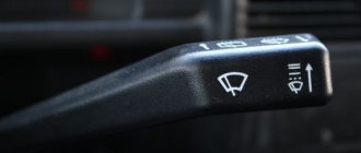
- We install steering column switches.
- Installing the steering wheel
- Reinstall the covers.
- We check the functionality of all mechanisms on the steering column.
Video on replacing the steering shaft coupling:
Sources used:
- https://avtoclic.ru/vaz-2115-14/rulevoe-upravlenie-avtomobilya-vaz-2115-14.html
- https://21092115.ru/VAZ-2108-2109/section-5-steering-control/device-features.html
- https://automotogid.ru/rulevaja-kolonka-vaz-2114-ustrojstvo/
- https://vaz-2114.info/vaz-2114-remont-rulevoj-rejki-svoimi-rukami-simptomy/
- https://remont2114.ru/kak-snyat-i-ustanovit-rulevuyu-kolonku-na-vaz-2113-2114-2115/
Troubleshooting in the steering of the Lada 2113, checking the steering mechanism of the Lada 2114, instructions for removing and installing the steering gear of the VAZ 2113, VAZ 2115, VAZ 2114. Steering device of the Lada 2115, repair manual for the steering gear of the Lada 2113 Lada 2114.
Place the Lada Samara 2 car on a lift or inspection ditch and perform the following operations:
Pressing out the steering rod ball joint pin from the swing arm of the suspension strut: 1 – swing arm; 2 – rod ball joint; 3 – puller A. 47035
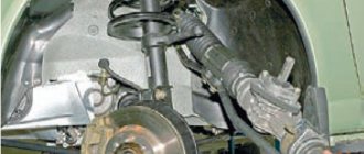
– lift the hood of the Lada Samara 2 car and, turning the car wheels to the right (left), undo the pin nuts of the ball joints, then press the pins out of the suspension struts using tool A. 47035;
Steering VAZ 2114: 1 – ball joint of the tie rod end; 2 – rotary lever; 3 – tie rod end; 4 – lock nut; 5 – traction; 6, 11 – inner tie rod ends; 7 – ball joint pin; 8 – protective cap; 9 – ball pin insert; 10 – bolts securing the steering rods to the rack; 12 – steering gear mounting bracket; 13 – steering gear support; 14 – connecting plate; 15 – protective cover; 16 – locking plate; 17 – steering gear housing; 18 – coupling bolt; 19 – elastic coupling; 20 – rack; 21 – rack support sleeve; 22 – damping ring; 23 – rubber-metal hinge; 24 – facing casing (upper part); 25 – steering wheel; 26 – steering column position adjustment lever; 27 – steering shaft mounting bracket; 28 – facing casing (lower part); 29 – intermediate steering shaft; 30 – protective cap; A - surface of the ball joint housing; B - surface of the rotary lever
– working from the interior of the body of a VAZ 2113, VAZ 2114, VAZ 2115, unscrew and remove the coupling bolt 18 of the steering shaft coupling flange; – remove the facing casing 24 and 28 of the steering column of the VAZ 2115; – disconnect the plug connector of the wires of the switches and the ignition switch; – unscrew the bolts and nuts securing the steering shaft to the body bracket and remove the bracket 27 assembled with the shafts and steering wheel 25, pulling them into the body interior; – working from the side of the engine compartment, unscrew the nuts securing the brackets 12 securing the steering mechanism to the front of the body; – move the steering mechanism forward until the gear comes out of the hole in the front body; – remove the VAZ 2113 steering mechanism assembly with rods, pulling it towards the right wheel;