Sensor check
If the abs sensor is faulty, it does not transmit the necessary commands to the system and the automatic braking system ceases to perform its functions: when braking, the wheels lock. If the message on the dashboard lights up and does not go out, then you need to urgently contact service.
The induction type sensor is an induction coil that works in tandem with a toothed metal disk located on the wheel hub. Often the cause of the malfunction is a broken wire. It is this fault that we determine using a tester, a soldering iron and pins for repair. The pins are connected to the connectors and the tester measures the resistance of the abs sensor, which must be within the limits specified in the operating manual. If the resistance tends to zero, then this indicates the presence of a short circuit. If it tends to infinity, then there is an open circuit.
Then the wheel is checked and the resistance is checked, it must be changed, in this case the sensor is working. If breaks are found during inspection, they must be repaired. Breaks should be connected only by soldering, not twisting, to avoid new breaks, oxidation, etc. Each device has its own marking, wire color and polarity. We must adhere to these data.
If the sensor is broken, you need to figure out how to remove the abs sensor and replace it. When choosing a device, you must first of all focus on quality.
To fully diagnose the sensors, you must not only check the contacts of the device itself with a tester, but you should also ring all its wiring. One of the reasons for incorrect operation is a violation of the integrity of the wiring. If the devices are working properly, then the resistance indicators are as follows:
- leg – front right abs sensor (7 – 25 Ohm);
- insulation resistance level – over 20 kOhm;
- leg – rear right abs sensor (6-24 Ohm).
Many cars have a self-diagnosis system. They display error codes on the information screen, which can be deciphered using the operating instructions.
What to do in this case, how to measure the resistance
As can be seen from the breakdown options discussed above, most of the problems are related specifically to the ABS sensor. In this case, information about the malfunction immediately manifests itself in the form of a warning lamp glowing.
The question is how to check the ABS sensor without spending additional money and calling for service. All that is required to solve the problem is a combination device or multimeter, a car manual and wires with PIN connectors. If possible, use an assistant.
To check the resistance, switch the multimeter to ohmmeter mode, then proceed as follows:
- Use a lifting device (jack) to lift the machine.
- Remove the wheel if it restricts access to the sensor.
- Remove the screw that holds the device in place (it's easy to find at the back of the hub).
- Remove the housing that protects the control unit, and then remove the connectors through which power is supplied to the controllers.
- Insert wires with PIN connectors into the circuit, and then connect them with the sensor and multimeter.
- Measure the resistance and check the resulting parameter with what the car manufacturer recommends.
- Check the wires for continuity and short circuit.
Have a helper spin the wheel several times. At the same time, monitor and record resistance parameters. If the sensor is working properly, then during rotation the resistance indicator will change. The normal parameters are as follows (measurements are made in relation to the sensor):
- Leg device - 5-26 Ohm.
- Ground device - from 20 kOhm or more.
Briefly about the principle of operation
The ABS function simulates the harsh, repeated pressure on the brake pedal experienced by drivers of older cars on slippery roads. Electronics uses this method of braking much more efficiently, locking and “releasing” the wheels several times per second. The operating algorithm is as follows:
- During sudden braking, the control unit monitors the behavior of the wheels using sensors.
- If one or more wheels stop rotating, the ECU issues a command to a hydraulic valve that releases fluid from that circuit. The pads stop holding the disc and rotation resumes.
- By comparing the readings of all meters, the controller makes sure that braking is not complete and closes the hydraulic valve, and the wheel is blocked again. The cycle, lasting a fraction of a second, is repeated until the machine stops completely.
Important! If the functionality of one or more sensors is impaired, the ABS will fail entirely, since the electronic unit will not be able to compare the behavior of the wheels.
The latest generation ABS sensor is a coil with a semiconductor element installed in a stationary part of the hub. In the immediate vicinity of it, a toothed ring is attached to the brake disc, whose rotation is monitored by a sensor. It happens like this: the controller supplies voltage to the device, and it constantly changes the resistance due to the passage of a series of teeth on a rotating ring.
When the amount of electrical resistance becomes constant, the ECU regards this fact as wheel locking and turns on the above-described algorithm. If the element fails, the ABS system is completely disabled.
Main types
The ABS sensor is read as the primary measuring part of the anti-lock braking system.
The device consists of:
- A meter placed permanently near the wheel;
- An induction ring (rotation indicator, impulse rotor) installed on a wheel (hub, wheel bearing, CV joint).
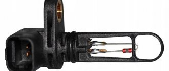
The sensors are available in two versions:
- Straight (end) cylindrical shape (rod) with a pulse element at one end and a connector at the other;
- Angled with a connector on the side and a metal or plastic bracket with a hole for a mounting bolt.
Two types of sensors are available:
- Passive - inductive;
- Active - magnetoresistive and based on a Hall element.
ABS allows you to maintain controllability and significantly increase stability during emergency braking
Passive
They are distinguished by a simple operating system, but are quite reliable and have a long validity period. Does not require a power connection. An inductive sensor is essentially an induction coil made of copper wire, in the middle of which there is a stationary magnet with a metal core.
The meter is located with the core to the pulse rotor in the form of a wheel with teeth. There is a certain gap between them. The rotor teeth are rectangular in shape. The opening between them is equal to or slightly larger than the width of the tooth.
While the vehicle is in motion as the rotor teeth pass near the core, the magnetic field penetrating the coil is constantly changing, forming an alternating current in the coil. The frequency and amplitude of the current are directly dependent on the speed of the wheel. Based on processing of this data, the control unit issues a command to the magnetic valves.
The disadvantages of passive sensors are:
- Relatively large dimensions;
- Poor accuracy of readings;
- They begin to function when the car picks up speed over 5 km/h;
- Triggered by minimal wheel rotation.
Due to frequent errors, they are installed extremely rarely on modern cars.
Magnetoresistive
The work is based on the property of ferromagnetic materials to change electrical resistance when exposed to a constant magnetic field.
The part of the sensor that controls changes is made of two or four layers of iron-nickel plates with conductors applied to them. Part of the element is installed in an integrated circuit that reads changes in resistance and generates a control signal.
The impulse rotor, which is a magnetized plastic ring in places, is rigidly fixed to the wheel hub. During operation, the magnetized sections of the rotor change the environment in the plates of the sensitive element, which is recorded by the circuit. Its output produces pulsed digital signals that enter the control unit.
This type of device controls the speed, direction of rotation of the wheels and the moment they come to a complete stop.
Magnetoresistive sensors record changes in the rotation of vehicle wheels with great accuracy, increasing the efficiency of safety systems.
Based on Hall element
This type of ABS sensor operates based on the Hall effect. In a flat conductor placed in a magnetic field, a transverse potential difference is formed.
Hall effect - the appearance of a transverse potential difference when a conductor with direct current is placed in a magnetic field
This conductor is a square-shaped metal plate placed in a microcircuit that includes a Hall integrated circuit and a control electronic system. The sensor is located on the opposite side of the pulse rotor and has the form of a metal wheel with teeth or a plastic ring, magnetized in places, rigidly fixed to the wheel hub.
The Hall circuit continuously produces signal bursts of a certain frequency. At rest, the signal frequency is reduced to a minimum or dies out completely. During movement, magnetized areas or rotor teeth passing by the sensing element cause changes in the current in the sensor, which are recorded by the tracking circuit. Based on the received data, an output signal is generated and sent to the control unit.
Sensors of this type measure speed from the beginning of the vehicle’s movement and are distinguished by the accuracy of measurements and the reliability of their functions.
Signs of a malfunctioning ABS sensor
The first sign of an ABS malfunction is a lit indicator on the instrument panel that does not go out for more than 6 seconds after turning on the ignition, or does not turn on when driving. A system breakdown is detected when the vehicle is moving at a speed of more than 25 km/h. There are quite a few problems that can happen with the anti-lock braking system, but the most common ones include the following:
- ABS sensor wire is broken or the controller unit is damaged. In this case, an error is displayed on the instrument panel, the system is turned off, and signals about changes in angular velocities are not given.
- The wheel sensor of the system has failed. When turned on, the system performs self-diagnosis and detects an error, but continues to function. The cause of the breakdown may be oxidation of the contacts, poor power supply to the sensor and a short circuit to ground.
- Receipt from an additional device of information about different angular speeds of wheels at different tire pressures or different tread patterns, when the wheels brake differently.
- Mechanical failure of elements - hub bearings, play and fracture of the rotor on the wheel sensor. In case of such failures, the system does not start. This also includes ABS pump failure.
The most vulnerable element of the system is the wheel sensor, which is located next to the rotating hub and axle shaft. Exposure to dirt and play in the hub bearings can damage the device, completely blocking the operation of the ABS. Along with the indicator signal on the instrument panel, the following signs indicate a sensor failure:
- The on-board computer displays an ABS system error code.
- There is no characteristic vibration or sound when pressing the brake pedal.
- The wheels lock during emergency braking.
- Appearance of the parking brake signal when it is disabled.
ABS device on Priora
Like most modern car systems, ABS is computer controlled. But in addition to the electronic control unit, it also includes several sensors and actuators. The entire system consists of several elements.
- Electronic control unit (ECU).
- Sensors on wheel hubs 4 pcs.
- Brake fluid pressure valves in the system 4 pcs.
- EVN (Electric Return Pump).
- Warning light on the instrument panel.
Despite all its apparent simplicity, this is a rather complex, high-tech system. Each sensor transmits data on the rotation speed of the Priora wheel to the electronic control unit. Based on the data received, the control unit sends a signal to the brake system valve, which, when you press the brake pedal, releasing pressure, prevents the wheels from completely locking and starting an uncontrolled skid of the car.
Anti-lock brake control unit in hydraulic unit
Structurally, on the Priora, the ABS ECU is mounted together with the EWH and valves that regulate the pressure into a single unit - the hydraulic unit. It is located on the front left side member of the vehicle. The hydraulic unit is connected to the entire system by a common wiring harness. It includes pipes for supplying brake fluid to the working cylinders. An EWH is also installed here, increasing the pressure in the system.
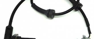
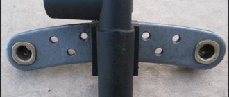
Wheel hub sensor
The sensors that supply wheel speed data to the control unit are made on the principle of a Hall sensor. By the way, most rotation sensors use exactly this principle: changing the voltage on the semiconductor of the sensor, depending on the passage of a control point on the rotating disk near it. It is in correlation with the signals from the ABS sensors that the control unit manipulates the valves.
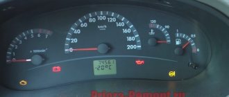
ABS malfunction warning lamp on the Priora instrument panel
What Priora drivers talk about – “the ABS sensor has come on” – is in fact a warning lamp for the serviceability of the anti-lock system. When the ignition is turned on, the orange “ABS” inscription will light up on the dashboard for about three seconds. If the system is working properly, then after three to four seconds the light will go out. In general, the principle of signaling from the “ABS sensor” is the same as from the warning lamp of the main ECU of the car, the well-known “check anger”.
Symptoms of a problem
To monitor the operation of the system, there is a yellow or orange indicator light. In normal conditions, when the ignition is turned on, a lamp on the instrument cluster is activated, then self-diagnosis of system elements is carried out and the icon automatically goes out.
Signs of breakdown of ABS system elements:
- turning on the system warning lamp while driving;
- stable wheel locking during heavy braking;
- absence of sounds indicating ABS operation (brake pedal vibration);
- the appearance in the memory of the electronic system of error codes related to the ABS.
If signs of ABS malfunction appear, operation of the vehicle is prohibited. The brakes, designed to work together with the anti-lock braking system, do not work correctly when it is turned off.
Ways to check functionality
To determine the condition of a part, we will perform a series of steps to diagnose it, moving from simple to complex:
- Let's check the fuses by opening the unit (inside the passenger compartment or in the engine compartment) and inspecting the corresponding elements (indicated in the repair/operation instructions). If a burnt component is found, we will replace it with a new one.
- Let's inspect and check:
- integrity of connectors;
- wiring for abrasions that increase the risk of a short circuit;
- contamination of the part, possible external mechanical damage;
- fixation and connection to ground of the sensor itself.
If the listed measures do not help to identify a device malfunction, it will have to be checked using instruments - a tester (multimeter) or an oscilloscope.
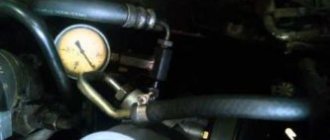
Tester (multimeter)
This method of diagnosing the sensor will require a tester (multimeter), instructions for operating and repairing the car, as well as PIN - wiring with special connectors.
The device combines the functions of an ohmmeter, ammeter and voltmeter
Tester (multimeter) is a device for measuring electric current parameters, combining the functions of a voltmeter, ammeter and ohmmeter. There are analog and digital device models.
To obtain complete information about the performance of the ABS sensor, you need to measure the resistance in the device circuit:
- We lift the car with a jack or hang it on a lift.
- Remove the wheel if it prevents access to the device.
- Remove the cover of the system control unit and disconnect the controller connectors.
- We connect the PIN to the multimeter and the contact socket of the sensor (the connectors for the rear wheel sensors are located inside the cabin, under the seats).
We connect the PIN to the tester and the contact socket of the sensor
- We measure the resistance (tester in ohmmeter mode) at the contacts of the device. We compare the readings of the device with the car’s operating manual, where the required parameters should be indicated.
- We check the electrical circuit by ringing the sensor wiring for a possible short circuit.
- We spin the wheel manually and at the same time measure the resistance - the tester readings should change depending on the rotation speed.
- We switch the tester to the “voltmeter” mode and measure the voltage on the sensor - we turn the wheel at a frequency of 1 rev/sec, monitoring the readings of the device. Voltage parameters from 0.25 to 1.2 V are considered optimal, but it should be taken into account that increasing the wheel speed necessarily increases them.
The device readings must correspond to the data specified in the repair and operation manual for a particular vehicle. If the device resistance:
- below the minimum threshold - the sensor is faulty;
- approaches zero - short circuit;
- unstable (jumping) at the moment of twitching of the wire - a violation of contact inside the wiring;
- infinity or no readings - wire break.
Attention! The resistance of the ABS sensors on the front and rear axles is different. The operating parameters of the devices are 1–1.3 kOhm in the first case and 1.8–2.3 kOhm in the second.
Video “Diagnostics of the ABS sensor”
How to check using an oscilloscope (with connection diagram)
In addition to self-diagnosis of the sensor with a tester (multimeter), it can be checked using a more complex device - an oscilloscope.
The device examines the amplitude and time parameters of the sensor signal
An oscilloscope is a device that studies the amplitude and time parameters of a signal, which is intended for accurate diagnosis of pulse processes in electronic circuits. This device detects problems with connectors, broken connections to ground, and broken conductors. The test is performed by visually observing the vibrations on the device display.
To diagnose the ABS sensor with an oscilloscope, you must:
- Fully charge the battery so that during the measurement you can observe voltage drops (jumps) on the connectors or conductors.
- Find the touch sensor and disconnect the upper connector of the part.
- Connect an oscilloscope to the contact socket.
Connecting the device to the ABS sensor connector (1 - toothed disc-rotor; 2 - sensor)
- Rotate the suspended wheel (by lifting the car on a jack or lift) at a constant frequency of 2-3 revolutions per second.
- Detect the amplitude of signal oscillations on the device display.
- Rotate the second wheel of the axle and similarly detect vibrations.
The serviceability of the ABS sensor is indicated by:
- equal amplitude of signal fluctuations when the wheels of one axle rotate;
- absence of amplitude beats when diagnosing with a sinusoid signal of lower frequency;
- maintaining a stable, even amplitude of signal fluctuations not exceeding 0.5 V when the wheel rotates at a frequency of 2 rps.
Note that an oscilloscope is a rather complex and expensive device. Modern computer technologies make it possible to replace this device with a special program downloaded from the Internet and installed on a regular laptop.
Video “Laptop instead of an oscilloscope”
Checking a part without instruments
The easiest way to diagnose a device without instruments is to check the magnetic valve on the induction sensor. Any metal product (screwdriver, wrench) is applied to the part inside which the magnet is installed. If the sensor does not attract it, it is faulty.
Most anti-lock brake systems of modern cars have a self-diagnosis function with errors displayed (in alphanumeric encoding) on the on-board computer screen. You can decipher these symbols using the Internet or the machine’s operating instructions.
Varieties of design
To calculate the angular speed of wheel rotation, 2 types of ABS sensor devices can be used:
- based on an inductive element. They are also called passive, since the sensitive element does not require external power, and the operating principle itself is based on the effect of electromagnetic induction. Despite the simplicity of design and reliability, such devices are becoming less and less common on modern cars. The main drawback of the design is that at low vehicle speeds it is impossible to adequately calculate the wheel speed;
- sensors based on the Hall effect. They are also called active, since the sensitive element needs power - a reference voltage. The signal produced by such speed sensors allows the ECU to more accurately calculate the wheel speed.
Design, principle of operation of inductive ABS sensors
Due to the operating principle of electromagnetic induction, the passage of comb teeth mounted on the CV joint body near the iron core provokes voltage surges. Due to the rotation of the wheel, a sinusoidal voltage fluctuation is recorded at the terminals of the ABS sensor; the frequency of the alternating voltage is directly proportional to the angular speed of rotation of the wheel.
The anti-lock brake system control unit registers and compares analog signals from all sensitive elements, which makes it possible to calculate the difference in the angular speeds of rotation of the wheels.
Multimeter test method
If you know how to use a multimeter, then you can check the passive ABS sensor using even the cheapest universal meter. Correspondence of possible faults and methods for their diagnosis:
- open circuit of the coil winding. Set the multimeter to diode testing mode. If the device shows infinite resistance, then there is an open circuit in the circuit;
- unsoldering the coil winding contacts. The nature of the failure is the same as in the case of a break;
- short circuit. To check, switch the multimeter to resistance measurement mode - ohmmeter, measurement range - up to 20 kOhm. Pre-measure the resistance of a previously working sensor or find out the standard value from the technical documentation. Typically, the resistance of serviceable elements ranges from 0.7 to 2.5 kOhm. It is important to take into account that the resistance of working sensors on the front and rear axles can differ significantly.
If the ABS sensor is removed from the car, then you can simulate the rotation of the master disk with any magnetic metal object.
Due to the aggressiveness of the installation environment, ABS sensors on motorcycles may have an electromagnet instead of a permanent magnet, which must be taken into account when checking without dismantling (the ignition must be on).
How to make your search easier
In order not to carry out testing with a tester on each wheel separately, remove the connector of the ABS control unit. The video shows that once you understand the pinout, you can quickly find which circuit has a short circuit or an open circuit.
Application of the Hall effect
The operating principle of the Hall sensor is based on the effect of a transverse potential difference when a conductor with direct current is placed in a magnetic field. A change in the magnetic field when a gear passes near the sensing element provokes the occurrence of rectangular voltage surges. The pulse frequency allows the ABS control unit to calculate the actual wheel speed.
Diagnostic method
Since the operating principle of the ABS sensor is based on the Hall effect, its independent testing is similar to diagnosing the speed sensor used in the speedometer, DPKV. A full check of the correctness of the signal can only be carried out with an oscilloscope, but for simple diagnostics a regular multimeter will do.
To check, you need to switch the tester to DC voltage measurement mode. Connect the test leads to the signal contacts of the sensor, having previously supplied power through an additional resistance (a resistor with a value of 480 Ohms to 1.2 kOhms) and connecting the ground contact to an unpainted part of the car body. If the element is completely faulty, the marker disc rotating with the CV joint will not provoke a change in high and low voltage levels.
Offline check
To operate, the sensitive element requires reference power, so without an external EMF source capable of delivering 9-12 V, it will not be possible to check the ABS sensor with a multimeter. It will also be necessary to include an additional resistor in the circuit (in the case of the Opel Vectra C brake system, as shown in the video, an element with a rating of 680 Ohms will be sufficient). The pinout of the connector can be found in the repair and operating manual for your car.
Since the sensitive element will be removed from the car, you can simulate the rotation of the marker disk by moving the magnet near the sensitive element.
General recommendations for diagnosing the ABS system
If the circuit is broken, the self-diagnosis of the ABS system will necessarily record the fact of a decrease in resistance in the sensor circuit and light up the ABS fault light on the dashboard. Some systems are capable of not only recording the fact of an error, but also calculating which wheel the breakdown occurred on. Therefore, if possible, the first step is to conduct computer diagnostics. On many cars, if more than 1 sensor breaks down, the system lights up not only the ABS fault light, but also the parking brake indicator, after which the ABS turns off.
Before starting diagnostics with a multimeter, make sure that the air gap between the sensor and the marker disk is set correctly, and that the cavities of the marker disk themselves do not have dense dirt or corrosive deposits.
Be extremely careful when removing the sensor. They often stick, but impacts or other use of brute force can damage the plastic case. When installing, ensure that there is a correct air gap between the drive disc and the sensing element.
How much does it cost to replace an ABS sensor on a Mazda 3: prices for services and what they consist of
Determining the cost of car repairs is the most pressing issue for a vehicle owner. We offer really good repairs at a competitive price. The cost of diagnosing and replacing an ABS sensor depends on several factors:
- Where exactly is the information reading device located, and how difficult is it to access? What parts will have to be removed to get close to the sensor.
- The amount of time that will have to be spent replacing equipment.
- Urgency of operations. The foreman requires additional payment for going on the second shift.
- Car model and make. In expensive jeeps or sedans, the process of removing and adjusting the sensor is more complicated than in budget vehicles.
- Reworking a failed renovation. Trying to save money, the owner tries to repair the car himself. This leads to the creation of additional difficulties for subsequent correct repairs in a car service center. The mounting socket may be bent due to carelessness or the contact group may break off completely; the technician will have to fix all this.
The cost of the ABS replacement service cannot be affected by the price of the sensor itself. The meter can be purchased at a car service center or brought with you if our kit does not have one. It should be remembered that the parameters of the new part must completely coincide with the old one. Mounting socket, length and number of connected wires.
How does ABS work?
With the advent of the new braking system, vehicle safety during emergency braking has increased. The system began to be installed in the 70s. The ABS system includes a control unit, a hydraulic unit, wheel brakes and speed sensors.
The main device of the ABS is the control unit. It is he who receives signals from touch sensors in the form of the number of wheel revolutions and evaluates them. The data obtained is analyzed and the system draws a conclusion about the degree of wheel slip, their deceleration or acceleration. The processed information is sent in the form of signals to the magnetic valves of the hydraulic unit, which performs the control task.
Pressure is supplied from the brake master cylinder (MBC), which ensures the appearance of pressure in the brake caliper cylinders. Thanks to the pressure force, the brake pads are pressed against the brake discs. Regardless of the situation and the force the driver presses the brake pedal, the pressure in the brake system will be optimal. The advantages of the system are that each wheel is analyzed and the optimal pressure is selected, thereby preventing wheel locking. Full braking occurs due to the pressure in the brake drive system, regulated by ABS.
This is the principle of ABS operation. On vehicles with rear-wheel drive and all-wheel drive, there is only one touch sensor, which is located on the rear axle differential. Information about the possibility of blocking is taken from the nearest wheel, and the command about the required pressure is transmitted to all wheels.
The device that controls magnetic valves can operate in three modes:
- With the inlet valve open and the outlet valve closed, the device does not prevent pressure from increasing.
- The inlet valve receives the appropriate signal and remains closed, without changing the pressure.
- The exhaust valve receives a signal that the pressure is decreasing and opens, while the inlet valve closes and the pressure decreases as the check valve turns on.
Thanks to these modes, the pressure decreases and increases in a stepwise system. If problems arise, the ABS system is deactivated and the braking system operates without its participation. On the dashboard, the corresponding indicator indicates problems with ABS.
How to check ABS sensors - visual inspection
- Check the condition of the ABS sensor power wires. Often it is the wiring that causes errors on the dashboard.
- Make sure the connection is secure. Contacts must be clean and non-oxidized.
- Check the condition of the ABS sensors. The sensors must be intact and the housing must not be damaged.
- Make sure that there is no play in the wheel bearing, that the brake system is in good condition, as well as the tightness of the turbocharger and brake pads. It happens that ABS sensors are “suspected”, but after replacement the problem remains, as a result it turns out that the problem was the wheel bearing or poor contact.
Alternatively, the ABS system can be checked using the ELM-327 scanner.
Analysis of diagnostic results
The problem with the ABS function does not always lie in the sensors. The culprits of system failure may also be the wires connecting the elements to the control unit. That is why it is necessary to carry out 3 measurements and draw the following conclusions based on the results:
- If the resistance of the ABS sensor tends to zero or, conversely, the device shows an infinity symbol, then there is a malfunction of the element itself. Another option is a violation of the insulation or a break in the section of conductors from the connector to the sensor.
- The tester shows that the resistance is within normal limits, but when the brake disc rotates, its value remains constant. There are two versions here: severe contamination of the gear ring (as an option - destruction) and, again, failure of the sensor.
- The absence of voltage in the supply line indicates a break in the electrical circuit coming from the controller.
In the first case, it is necessary to remove the device from the hub and inspect the wires for fractures, breaks or short circuits. To be sure, measure the resistance again, while moving the conductors. If the result is negative, buy and install a new part.
If the resistance remains the same, get to the gear ring, clean it thoroughly and inspect it. If you find mechanical damage, it is better to replace the spare part.
Advice. Sometimes unscrupulous or ignorant auto mechanics damage the ring when repairing the suspension, or even throw it away completely. When picking up your car from a mechanic, always check that this important part is present.
In the case when there is no voltage in the controller circuit, you should ring this section of the wiring. How to do it:
- Find out where the electronic control unit for the hydraulic valves is located. For example, in a Chevrolet Aveo it is located behind the brake fluid reservoir, and in a Renault Megane it is located on the side of the alternator drive belt.
- Remove the block from the ECU and clean the contacts. Find the pinout of the wires or track them by color.
- Place a shorting jumper on the block located near the wheel. Test the circuit with an ohmmeter or a regular light bulb with a battery.
The easiest way to find the ECU if there is no documentation for the car is to follow the brake pipes leading to the hydraulic unit. The latter stands next to the controller or is connected to it by a bundle of wires.
If an open circuit is detected, you will have to look for the defect along the entire line in order to eliminate it. The work is quite complex, so it should be entrusted to an experienced auto electrician.