Site about off-road vehicles, SUVs, off-road vehicles
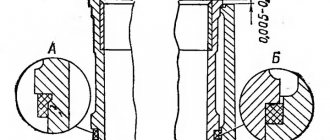
With the UMZ-421 engine not running, the ignition timing setting angle at the end of compression in the first cylinder should be 5 degrees before top dead center. In this case, the second mark on the damper part of the engine crankshaft pulley should be located opposite the indicator rib of the timing gear cover.
Setting the ignition timing on the UMZ-421 engine.
— remove the cover of the sensor-distributor; — Unscrew the spark plug of the first cylinder; — close the hole for the spark plug of the first cylinder with your finger; — turn the engine crankshaft until air begins to escape from under the pin. This will happen at the beginning of the compression stroke; - making sure that compression has begun, carefully turning the engine shaft, align the hole on the crankshaft pulley with the pin on the timing gear cover; — making sure that the slider electrode is installed against the terminal on the cover marked with the number “1” , the terminal for the ignition wire of the first cylinder spark plug, tighten the bolts so that the octane-corrector indicator of the distribution sensor coincides with the middle division of the octane-corrector; — loosen the bolt securing the octane corrector plates to the sensor-distributor body; — holding your finger on the slider against its rotation, to select the gaps in the drive, slowly turn the housing until the mark on the rotor aligns with the arrowhead on the stator of the sensor-distributor; — tighten the bolt securing the octane corrector plate to the sensor-distributor body and install the cover of the sensor-distributor in place; — install high-voltage wires into the cover of the sensor-distributor in accordance with the operating order of the cylinders 1-2-4-3, counting counterclockwise.
After each setting of the ignition timing, check the accuracy of the ignition setting by listening to the engine while the car is moving. For this :
— warm up the engine to a temperature of 60-90 degrees, driving in direct gear on a flat road at a speed of 20-40 km/h; — give the car acceleration, sharply, all the way, by pressing the throttle pedal; - if a slight and short-term detonation is heard, then the ignition timing is set correctly; — in case of strong detonation, turn the housing of the distribution sensor one division of the octane corrector scale counterclockwise, each division of the scale corresponds to a rotation of the crankshaft by an angle of 4 degrees; — in the complete absence of detonation, turn the sensor-distributor housing one notch clockwise.
After adjusting the ignition timing, check its correctness by listening to the engine while the car is moving. It is necessary to adjust the ignition so that only a slight detonation is heard when the engine is under heavy load. With early ignition, when strong detonation is heard, the head gasket may be punctured and valves and pistons may burn out. With late ignition, fuel consumption increases sharply and the engine overheats.
Precise ignition setting using a strobe light.
A more precise setting of the ignition timing is made using a strobe light. To do this you should:
— connect the strobe sensor to the high voltage wire of the spark plug of the first cylinder; — start and warm up the engine; — check the engine and, if necessary, adjust the crankshaft speed at idle within 700-750 rpm; — turn on the strobe and point it at the indicator rib on the camshaft gear cover, while the indicator rib and three fixed marks on the crankshaft damper pulley should be visible.
When the ignition is installed correctly, opposite the indicator edge there should be an area between the first and second marks of the damper pulley. If the position of the indicator rib and marks does not correspond to the specified ones, then it is necessary to loosen the bolt securing the sensor-distributor to the drive housing and, with the engine running and the strobe light on, rotate the housing of the sensor-distributor to the optimal position of the indicator rib and marks.
Source
Tip 3: How to set contactless ignition
A positive setting of the ignition timing in a contactless ignition system makes it possible to operate the car in comfortable conditions. Otherwise, the engine does not develop full power and fuel consumption increases. set the contactless ignition not only at a service station, but also on your own.
Instructions
1. Install the crankshaft in a position that corresponds to the ignition timing of 5 degrees. In this case, the middle mark on its pulley must coincide with the pin on the block cover, this will indicate the end of the compression stroke in the first cylinder, or top dead center (TDC). When the ignition distributor sensor is not removed from the engine, the TDC of the first cylinder can be determined by removing the distributor cap. The slider should be located opposite the internal contact of the cover, the one that is connected by wire to the spark plug of the first cylinder.
2. If not, you need to unscrew the spark plug of the first cylinder. Close the hole with a paper stopper, take the crank or ratchet key and rotate the crankshaft. TDC will be in the required place as soon as the air pushes the plug out.
3. Loosen the octane corrector screw with a 10mm wrench and set its scale to “0” (middle of the scale). Take a 10mm wrench and loosen the screw securing the octane corrector plate. Turn the housing of the sensor-distributor until the marks align: the arrow on the stator and the red mark on the rotor. Hold the sensor in this position and tighten the screw.
4. Make sure that the slider is opposite the contact of the first cylinder on the distributor sensor cover. Check the order of connecting the high-voltage wires of the engine cylinders. It is 1-2-4-3, if you count counterclockwise, starting from the first cylinder.
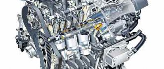
Engine UMZ-421 UAZ: Technical characteristics
In today's market conditions, constant modernization of power plants is necessary, taking this fact into account, the management of the automobile plant in Ulyanovsk began producing the 421 UAZ engine. The unit replaced the “417” motor, which had proven itself in terms of reliability and simplicity.
The follower does not lag behind, having inherited the sought-after traits from the ancestor. Thus, “421”, along with survivability and practicality, shows increased traction and speed characteristics, delighting users. In addition, the unit has increased power and torque impulse. I am glad that the modification has not lost touch with its ancestor in terms of replacement on outdated vehicles. “417” can easily be changed to “421” without additional modifications.
Motor UAZ-421 “Euro-4”:
Engine Description
The UAZ-421 engine has been produced at the plant in Ulyanovsk since 1993. The motor is used for installation on UAZ cars: “469”, “Bukhanka”, “Bars”, “31519”, “Hunter”, etc. The designers decided to replace the outdated “417” unit with a motor, introducing new trends into it.
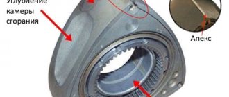
Thus, an original design of an aluminum frame was used, in which dry liners with thin, cast-iron walls are filled. This made it possible to increase the cross-section of the chambers to 100mm, and leave the same size between the cylinders, 116mm. The solution had a positive effect on the service life of the unit, since rigidity increased and the tendency of the cylinders to become “oval” during operation decreased.
The changes affected the piston; the distance between the bottom of the displacer and the pin axis was reduced by 7.5 mm, which reduced the weight of the product. In addition, the length of the connecting rod has increased by 7 mm, reducing the force on the side surface.
Since the distance between the axes of the chambers remained unchanged, most of the components of the “417” and “421” power plants remained mutually interchangeable. The unification affected the cylinder heads, part of the chamber volume was transferred to the piston bottom, in the form of a cone. This increased the volume of the combustion chamber by 12 cm3.
The engine uses a disposable oil filter element, borrowed from the VAZ-2101. The rear crankshaft oil seal is made as a full rubber seal, rather than stuffed with cord.
The negative aspects of the UAZ-421 engine are insufficient quality of components, and increased fuel consumption. Fitting causes frequent leaks of liquids, and surface treatment affects the resource and potential of the unit.
Technical characteristics of the UAZ-421 engine
UAZ 421 engine technical characteristics:
| Explanation | Meaning |
| Using the motor | “Loaf”, “Bars”, “Hunter”, etc. |
| The motor is produced | 1993 to today |
| Engine fuel | A-76(92) |
| Motor, environmental standards | "Euro 0-4" |
| Ticks, (number) | «4» |
| Engine volume, (l) | 2,890 |
| UAZ frame, (alloy) | aluminum |
| Number of cameras, (pcs.) | "four" |
| Motor chamber, (location) | row, vertical |
| Valves, (pcs.) | "eight" |
| Spark plugs for 421 UAZ engine, potassium number | 11/14/17 |
| Camera operation, (order) | «1243» |
| Chamber cross-section, (m) | 0,1 |
| Gap between the extreme points of the displacer, (m) | 0,092 |
| Compression | «7», «8,2», «8,8» |
| Motor power, (hp) | 98-125 |
| Torque turning the shaft, (Nm) | 220 |
| Unit weight, (kg) | 170 |
| Motor operating time, (km) | 250000 |
| Engine mixture formation | carburetor/injector |
| Fuel consumption: highway*mixed (l/100) | 10*11 |
| Lubrication supply | pressure + steam |
| Lubricant volume, (l) | 5,8 |
| Engine lubricant | 5(10)W-30 (40), 15(20)W-40 |
| Lubrication loss, (l/thousand km) | 0,1 |
| Reducing engine temperature | Liquid, closed, fan |
Being the successor to the UAZ-417, the new modification received a larger volume and, as a result, larger exhaust valves (39mm). It is noteworthy that the injector began to be installed on cars relatively recently, due to which fuel efficiency, in comparison with a carburetor, has improved. The disadvantage of the model is the lack of hydraulic compensators, so the valve clearance of the UAZ 421 engine requires adjustment every 10,000 km.
UAZ camshaft (cast iron):
Engine Modifications
Trying to eliminate the shortcomings, the designers constantly refined and corrected the unit. As a consequence, fixation of changes led to the appearance of modifications of the model, the performance characteristics of which differed.
The base engine “4218.10”, which became the basis for the rest of the modifications, had a defect due to which coolant penetrated into the oil through aluminum pores. It was not possible to eliminate the defect by replacing seals and gaskets. The designers used the technology of impregnating the frame with resin, after which the defects disappeared, and the modification received the marking “421.10”.
In order to increase the impulse at lower speeds and the power of the unit, an improved resonator was supplied to the product and the compression ratio in the combustion chamber was increased. Modification “421.10-30” after modification is installed on the Gazelle car. The same engine with a modernized power supply and exhaust gas removal mechanism is marked as “4215.10-30”.
In order to reduce fuel costs, UAZ engines used for buses and trucks began to be converted to fuel with a lower octane number “A-76” (“4215.10-10”).
The appearance of the UAZ 421 engine injector, which was intended for installation on vehicles with all-wheel drive, led to the creation of a new modification “4213.10”. A special feature of the engine is the use of a cast iron camshaft, which made the modification stand out in comparison with a carburetor product. The same motor with a modified fan drive was installed on the Gazelle, product identifier “4216.10”.
Types of UAZ with carburetor (421...):
Frequency of motor monitoring and adjustments
When calculating the power plant, the designers determined the operating life of the unit at the level of 250,000 km. To achieve the specified period, the following is configured and adjusted:
Replacing the oil filter:
The same deadlines for the work are observed after the overhaul, regardless of how many manipulations are performed. For engines running on gas and gasoline, seals are replaced more often. You can also read about the UAZ Patriot Razdatka.
Valve adjustment 421 UAZ engine
Since the engine does not technically provide for the installation of hydraulic valve compensators, it is necessary to adjust the gap in the gas distribution mechanism through the established gap on the unit. The minimum distance traveled before adjusting the valves is 5000 km. If malfunctions in the operation of the motor are detected, the procedure must be carried out earlier.
Signs of incorrect valve adjustment settings:
The process of adjusting the valve clearances is accompanied by a parallel adjustment of the clearance in the rocker arms.
In addition, after the work is completed, the ignition of the unit is adjusted. The gap parameters are as follows:
Engine ignition installation
An ignition device used in a power plant, a product without which the operation of the engine is impossible. The correct operation of the engine and the combustion of the fuel charge are directly related to how to install the ignition on the UAZ 421 engine. Since hydraulic valve compensators are not structurally provided, manual adjustment is carried out, providing:
The ignition operation must be additionally monitored while driving the vehicle. Briefly press the foot speed lever to full speed, having previously accelerated the car to a speed of 60 kilometers per hour. Detonation for 1-3 seconds indicates that the settings are correct. Longer - the advance angle is exceeded, no detonation - the advance angle is insufficient. In the last two cases, the setting is repeated.
Source
Instructions for installing and configuring the ignition on a UAZ
Starting the engine of any car is possible due to the ignition of the combustible mixture in the cylinders of the power unit. To ensure normal operation of the engine, proper adjustment of the ignition system (IS) is necessary. In addition, all elements, including the coil, distributor of the UAZ vehicle and other components must always be in working order.
Blog about UAZ
With the UMZ-421 engine not running, the ignition timing setting angle at the end of compression in the first cylinder should be 5 degrees before top dead center. In this case, the second mark on the damper part of the engine crankshaft pulley should be located opposite the indicator rib of the timing gear cover.
Setting the ignition timing on the UMZ-421 engine.
— remove the cover of the sensor-distributor; — Unscrew the spark plug of the first cylinder; — close the hole for the spark plug of the first cylinder with your finger; — turn the engine crankshaft until air begins to escape from under the pin. This will happen at the beginning of the compression stroke; - making sure that compression has begun, carefully turning the engine shaft, align the hole on the crankshaft pulley with the pin on the timing gear cover; — making sure that the slider electrode is installed against the terminal on the cover marked with the number “1” , the terminal for the ignition wire of the first cylinder spark plug, tighten the bolts so that the octane-corrector indicator of the distribution sensor coincides with the middle division of the octane-corrector; — loosen the bolt securing the octane corrector plates to the sensor-distributor body; — holding your finger on the slider against its rotation, to select the gaps in the drive, slowly turn the housing until the mark on the rotor aligns with the arrowhead on the stator of the sensor-distributor; — tighten the bolt securing the octane corrector plate to the sensor-distributor body and install the cover of the sensor-distributor in place; — install high-voltage wires into the cover of the sensor-distributor in accordance with the operating order of the cylinders 1-2-4-3, counting counterclockwise.
After each setting of the ignition timing, check the accuracy of the ignition setting by listening to the engine while the car is moving. For this :
— warm up the engine to a temperature of 60-90 degrees, driving in direct gear on a flat road at a speed of 20-40 km/h; — give the car acceleration, sharply, all the way, by pressing the throttle pedal; - if a slight and short-term detonation is heard, then the ignition timing is set correctly; — in case of strong detonation, turn the housing of the distribution sensor one division of the octane corrector scale counterclockwise, each division of the scale corresponds to a rotation of the crankshaft by an angle of 4 degrees; — in the complete absence of detonation, turn the sensor-distributor housing one notch clockwise.
How to set the ignition
In order to correctly adjust the UAZ ignition the first time, you should adhere to the following recommendations:
- First you need to remove the cover that belongs to the distributor with the rotor. After this, the size of the gap between the contacts is checked and checked against established standards. Its maximum size can be from 0.35 to 0.45 mm, no more and no less. This plays an important role here and directly affects the operation of the engine. If the gap is too small, it will produce a small spark and because of this, the unit may operate intermittently. And if it is too high, the spark will not occur at all. If the gap deviates from the previously stated standard, it can be adjusted. Adjustment is best done using a set of feeler gauges. Having made a normal gap and checking it again, the rotor can be returned back and proceed to the next steps.
- Next, you need to carefully unscrew the spark plug of the first cylinder with a specially designed wrench. The resulting hole must be closed with your finger and held, while turning the crankshaft with the starting handle. When the compressed air begins to push the pin out of the hole, which means the start of the stroke, you need to continue turning the handle until the holes on the pulley and pin coincide. The rotor should be located opposite the internal contact of the cover, connected to the high-voltage wire from the spark plug of the first cylinder.
- Then you need to turn the octane corrector plate with the distributor. It is necessary to ensure that the mark coincides with the middle mark on the scale of the plate. Then, having completed this operation, you should slightly turn the distribution mechanism housing counterclockwise. Do this until the contacts of the distributor connect to each other.
- Next you need to connect the control light. The first contact must be connected to the low voltage terminal, and the second to the machine ground. It is possible to connect the lamp to the vehicle body.
- Next, you need to activate the ignition and start turning the distributor to the left until the lamp lights up. After this you need to stop. If tanning does not occur, then you should repeat everything all over again and wait for a positive result. You can't move on without it.
- Then, when everything works out, you need to tighten its mounting bolt on the distributor. When the cover is in place, you need to check how everything is adjusted. This must be done starting from the very first cylinder, to the right. At this point the work can be considered complete, and if everything is done correctly, the motor will function correctly and without interruption.
Setting the Ignition Timing on Your Harley
Check ignition timing:
At every 5,000 mile (8,000 km) service interval. Check the correct RPM and Ignition Timing is as follows:
1. See Figure 0. Thread the TIMING MARK VIEW PLUG (Part No. HD 96295-65D) into the timing check hole. Be sure to look at the plugin, it does not touch the flywheel.
1a. See Figure 1. Find the correct evaluation time for your engine. If a shop manual is not available, remove the spark plugs, crank the engine until the front piston is at TDC on compression, press and identify the TDC mark on the flywheel.
2. Connect the INDUCTIVE TIMER leads to the front spark plug cable, battery positive terminal, and ground.
3. Make sure the vacuum hose is properly installed on the carburetor and on the vacuum electric switch (V.O.E.S.).
4.Start the engine. Set the engine speed by turning the idle speed screw clockwise to increase speed or counterclockwise to decrease speed.
Communities › UAZ drivers › Blog › Underwater ignition on UMP 421. Review and installation.
Comments 13
do the spark plugs need to be changed? the spark became more powerful. Or am I wrong? tell. if so, which ones?
Please tell me what the wire braid is from and is it possible to use one Boshev coil instead of 2?
unfortunately not. but there are videos with his participation on the channel.
Yes, it has already been discussed a bunch of times on UAZBUKE... the plate must be U-shaped, otherwise the axial play will damage the sensors. At one time I assembled everything on one sensor and a two-channel switch. True, I still had two sensors and the switches were also installed in pairs, but this was simply duplication of systems, in case something failed...
Ignition installation for various types of engines
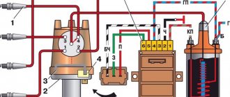
DIY scheme:
Characteristics of a centrifugal regulator
The UMZ-421 engine , used in Gazelle and UAZ vehicles, uses a classic distributor with a mechanical breaker, that is, a contact ignition system. Setting the ignition timing on the UMZ-421 engine is done by manually adjusting the position of the thin spring in the distributor through a special window. The method is:
For the PD-23 engine (starting motor for tractors) the permissible gap value is. Between the electrodes of the PD-23 spark plug is 0.6-0.7 mm. Before installing the PD-23 ignition on the engine, it is necessary to adjust the gap. All this concerns – PD – 23 .
DIY circuit for PD engine–23:
1 – mark on the clutch housing; 2 – “Clamp” mark on the flywheel; 4 – lead contact; 5 – terminal designation; 6 – axis; 7 – angle between the vertical axis of the magneto and the axis of the cams, equal to 5-10°; 8 – vertical magneto axis; 9 – arrow of the direction of rotation of the magneto rotor; 10 – starting accelerator cam; 11 – slot on the starting accelerator; 12 – TDC-1c mark on the flywheel; a – installation of ignition of the starting engine on the flywheel; b – rear view of the magneto; c – front view of the magneto.
On the D-144 diesel power unit, fuel injection advance is set by rotating the camshaft toothed pulley. On the D-65 YuMZ (tractor of the YuMZ series, it is designated D-65 YuMZ) this procedure is performed by rotating the crankshaft. The ZMZ-409 is equipped with a microprocessor ignition system. According to numerous reviews, the weakest point of the ZMZ-409 is the ignition coil.
Strobe light for installing the ignition - you can install the ignition on the UMZ-421 with your own hands using a strobe light. To do this, the strobe sensor is connected to the high-voltage wire of the spark plug of the first cylinder on a warm engine, after which the strobe beam is directed to a mark located on the timing cover. This setting of the ignition timing is the most accurate; it must be set correctly.
You can make a strobe light for installing the ignition yourself . The cost of a simple device for determining lead angles will be significantly lower than that of industrial analogues, and the measurement accuracy and durability of the device will be even better. In order to properly create a homemade (with your own hands) strobe, you only need a cheap pocket flashlight (there are plenty of these in any electrical appliance store), connect a piece of antenna wire and a few other parts.
Diagram for clarity:
Strobe circuit for ignition installation
Assembling the MMZ D-240 and D-245 devices with your own hands takes about 30 minutes. MMZ D-240 and D-245 engines need to adjust the position of the crankshaft impulse wheels before setting the fuel ignition timing. And also, the drive of the MMZ D-240 and D-245 fuel pump gearbox.
Note that there are diesel engines D-245.7, D-245.9, D-245.12S, they are intended for buses, do not confuse the usual D-245!
Adjusting the position of the crankshaft impulse wheels
Setting the ignition timing of UAZ-3151
1. Disconnect the wire from the negative terminal of the battery.
2. Remove the distributor cap.
3. Rotate the crankshaft until the compression stroke begins.
To determine this moment, you need to unscrew the spark plug of the 1st cylinder and close the hole for the spark plug with your finger.
At the beginning of the compression stroke, air will begin to escape from under the finger.
4. Carefully rotate the crankshaft until the second mark on the pulley coincides with the boss on the camshaft sprocket cover.
This mark corresponds to an ignition timing angle of 5° on an engine with an exhaust gas recirculation system (for engines without exhaust gas recirculation systems, install the pulley so that the middle of the pulley between the second and third marks is against the tide on the camshaft sprocket cover, which corresponds to an ignition timing angle of 2°) .
5. Loosen bolt 3 securing the distributor. Set pointer 2 of the octane corrector to the middle of scale 1 and tighten bolt 3.
Loosen bolt 4 securing the octane corrector plate to the distributor body.
Lightly press the slider with your finger against its rotation (clockwise) to select the gaps in the drive.
Holding the slider, slowly turn the distributor housing 5 until the red mark “ A”
on the rotor with arrow "
B"
on the stator.
Tighten bolt 4 securing the octane corrector plate to the distributor body.
6. Install the distributor cap and connect the high-voltage wires in accordance with the operating order of cylinders 1-2-4-3.
7. Check the ignition timing setting. To do this, warm up the engine to a temperature of 80-90 °C and, moving on a flat road at a speed of 30-40 km/h, sharply press the accelerator pedal all the way.
In this case, detonation should be heard briefly.
If detonation is not heard, it means the ignition is late.
If the detonation is too strong, it means the ignition is too early.
When igniting early, turn the distributor body one scale division towards “+” (counterclockwise), and when igniting late, turn towards “-” (clockwise).
Then check the ignition timing again while the car is moving, as described above.
8. More precise setting of the ignition timing can be done using a strobe in accordance with the instructions included with the strobe.
Description of SZ on UAZ
How is the ignition circuit installed, configured and adjusted on the AUZ 417 or any other? We will talk about this below. But first, let's understand the principle of operation of the node, as well as the types of SZ.
Operating principle of SZ
As already said, the ignition on an UAZ performs one of the main functions when starting the power unit. Thanks to this system, the procedure for igniting the air-fuel mixture in the cylinders of the power unit is carried out by supplying a spark. The spark is directly supplied to the spark plugs; one spark plug is installed on each cylinder. All of these safety devices operate in sequence mode, igniting the combustible mixture in the required period of time. It is also necessary to take into account that the ignition system on cars not only provides a spark, but also determines its strength.
The vehicle battery is not able to produce the voltage and current required to ignite the mixture, since this device only produces a certain amount of current. The help comes from the ignition system, the purpose of which is to increase the power of the car’s battery. As a result of using the SZ battery, it is possible to transmit sufficient voltage to the spark plugs to ignite the mixture.
Types of ignition systems
Today there are three main types of ignition systems that can be installed on cars:
Ignition system UAZ 469
To start the engine of any vehicle, it is necessary that the combustible mixture ignites at the right moment in the combustion chamber. Effective operation of the piston system is achieved by correctly setting all parameters. The UAZ 469 ignition system allows you to operate the vehicle regardless of climate, temperature, humidity and other external factors.
The ignition of the UAZ 469 ensures that all elements are in good working order and flawlessly perform their assigned functions. For UAZ 469, the ignition circuit consists of the following components:
- ignition coil UAZ 469;
- distributor;
- tourniquets;
- switch;
- candles.
Each individual component of the electrical circuit must not allow breakdown to the car body and current leakage.
The ignition of a UAZ 469 car includes the following elements:
- battery;
- mass button;
- voltage regulator relay;
- generator;
- ammeter;
- ignition switch UAZ 469;
- breaker-distributor contacts;
- distributor;
- capacitor;
- ignition distributor-distributor cover;
- slider;
- spark plug;
- high voltage wire;
- additional resistance;
- additional starter relay;
- ignition coil;
- starter.
The ignition order of the UAZ 469 is strictly regulated; the spark occurs exactly in the specified sequence. An important point is not only the timeliness of the spark supply, but also its size. If the slightest interruption occurs, the entire chain is reconfigured.
A car battery is not designed to produce sufficient current and voltage required to ignite a combustible mixture. The charging current is only capable of spinning the engine flywheel for a short time. For stable operation of the engine, the entire ignition system of the vehicle must begin to fully function.
This important component of the machine is designed to significantly increase the power characteristics of the battery. Proper ignition, together with the battery, sends the spark plugs the sufficient volume and current required to reliably ignite the fuel mixture.
How to use the ignition timing indicator to set the ignition timing
Note. This post may contain affiliate links. This means we may receive a small commission at no extra cost to you on qualifying purchases.
You will need to adjust the timing on the car for many older models (those with a distributor) to maintain the best performance. If you neglect timing, you could experience poor gas mileage, less power when you hit the gas, and ultimately worsen problems that could interfere with your engine's performance.
Although you can have a mechanic adjust the timing for you, it is a fairly simple process and you can save a lot of money if you learn how to do it yourself. Double check your car before you jump in.
Most produced since the early 90s have an electronic ignition system and do not require this maintenance. In these cases, it is best to use a scanning tool.
What are deadlines?
Before we learn how to set ignition timing, we need a little lesson on how engines work. Simply put, an engine works by using small explosions of gasoline to force the pistons to move up and down.
This movement turns the motor, which in turn turns the gears and spins the wheels. This ignores a lot of other processes that are happening at the same time, but it is the main function of your engine.
We use electric spark plugs to ignite gasoline, so when we talk about timing a car, we're talking about making sure the spark plug ignites at the perfect moment.
More specifically, we want to fire the plug just before the piston reaches its peak in the up-down motion. If this is a little vague, it will make more sense when we talk about the complete engine cycle.
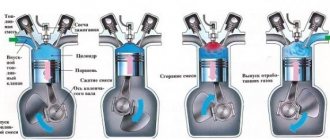
Four stroke
To keep the engine running, it goes through four steps (called strokes) in sequence. These strokes are called intake, compression, power and exhaust.
During intake, air and fuel are drawn into the cylinder for combustion. The compression stage is when the piston applies pressure to the air-fuel mixture.
Operating principle of the ignition system
Ensuring and maintaining timely ignition of the air-fuel mixture for the efficient functioning of the internal combustion engine is the main task of ignition. This occurs in strict accordance with the established operating order of the engine cylinders. An ignition coil 16 is connected in series to the electrical circuit along with an additional resistance 14. It is automatically closed when the engine is started by the starter.
This significantly increases the breaking current of the primary circuit. Ignition coil 16 creates high-frequency pulses in the vehicle's on-board electrical system. High voltage flashes create a breakdown of the spark gap in the spark plugs 12, screwed into the top point of each cylinder, where the working fuel mixture is compressed.
The coil consists of primary and secondary windings. The primary winding is wound on top of the secondary. Inside the coil there is a core and a ring magnetic circuit. Both of these elements are made of special electrical steel. Reliable sealing of the coil is carried out by a carbonite cover in a casing with a rubber gasket.
Transformer oil is poured into the casing for cooling. This material significantly increases the insulation of the windings and effectively removes heat from the coil body. To avoid damage to the coil and its overheating, it is not recommended to leave the ignition on in a car when the engine is not running.
Distributor 8 distributes high voltage pulses to all cylinders of the internal combustion engine strictly in the established sequence. The distributor or breaker-distributor is installed in a standard place to the left of the engine cylinder block. The mechanism is driven by the oil pump roller. The roller rotates counterclockwise from the lid side.
How to set the ignition timing on a UAZ
How to set the ignition timing on a UAZ
The operation of the engine in a car is impossible without correctly set ignition timing. This is visible not only when starting the engine with the starter, but also when the car itself is moving. Discomfort when driving increases due to a drop in engine power and its uneven operation, gasoline consumption increases and, most importantly, on the road the car begins to behave unstably, in some cases it may simply suddenly stall. How to set the ignition timing on a UAZ
If you have even a little skill in car construction, you can do this work with the ignition yourself.
What are the ignition systems on the UAZ 469
Contact ignition on UAZ 469
. Now it is recognized as obsolete. However, domestic manufacturers continue to use it. The system launches a pulse of a certain power. This impulse comes from the ignition distributor. The contact ignition circuit of the UAZ 469 is simple and uncomplicated. This is its advantage. The driver can fix any malfunction and make adjustments with his own hands. The prices of components are low.
Transistor or contactless ignition of UAZ 469
. Contactless ignition systems are installed on many types of vehicles. It has a number of advantages over the contact design. The spark produced by such a device is much more powerful. This occurs due to an increased level of electrical voltage in the secondary winding of the ignition coil. The transistor ignition system is equipped with an electromagnetic mechanism. It ensures stable, constant operation of the entire system, uninterruptedly transferring energy to components, parts, and mechanisms. Correctly configured ignition with an efficient internal combustion engine guarantees high power and significant fuel savings. Long-term reliable performance is ensured by compliance with the frequency of maintenance of the distributor drive. It must be lubricated and adjusted every 10,000 km. The difficulty of repair is a disadvantage of the contactless ignition system. It cannot be repaired independently, since this requires special diagnostic equipment, available only in service centers and service stations.
Electronic ignition on UAZ 469
. This type of ignition is the most technologically advanced, but at the same time expensive. Modern car models are equipped with similar devices. It has complex technology that provides not only high torque, but also a number of other engine indicators. Advantages: simple adjustment of the advance angle, no mandatory check of contacts for oxidation. In engines equipped with electronic spark protection, the fuel mixture burns 100%. Repairs must be carried out only at a service station.
Underwater ignition on UAZ 469
. This is a sealed ignition system, in which there is no fear of flooding with water, falling into deep holes, or driving in open areas during snow and rain. When the ignition is normal - contact or non-contact, 50% of the spark power is actually lost inside the distributor, between the cover and the runner. Let's find out why this happens.
There is a small gap between the electrical contacts, which are the distributor cap and the slider. To pass electrical energy through this space, most of the additional current is expended. With contact ignition, for these purposes, another part of the energy is spent on the functioning of the cam.
The underwater ignition is designed in such a way that the spark from the coil directly hits the spark plug. Carrying out this process, it does not lose its main power, except for the resistance of high-voltage wires. Here the loss of power is quite insignificant, so it can be ignored.
It is worth noting that on most foreign-made cars, a coil is placed separately on each cylinder, which is located immediately on the spark plug, and the loss is accordingly quite insignificant.