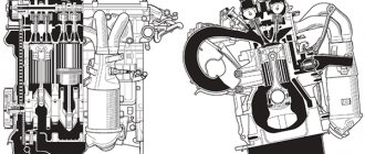
Engines ZMZ-402 and ZMZ-4021
Bolt for fastening the cover of the timing gears 11-16 (1.1-1.6) Nut for fastening the cover of the timing gears 12-18 (1.2-1.8) Nut for fastening the cover of the pusher box 12-18 (1.2-1.8 ) Cylinder head mounting nut 85-90 (8.5-9.0) Cylinder head rear cover mounting bolt 11-16 (1.1-1.6) Connecting rod cover mounting bolt nut 68-75 (6.8- 7.5) Flywheel mounting nut 78-83 (7.8-8.3) Crankshaft pulley mounting bolt 11-16 (1.1-1.6) Crankshaft pinch bolt (ratchet) 170-220 (17-22 ) Bolt for fastening the thrust flange of the camshaft 11-16 (1.1-1.6) Bolt for fastening the camshaft gear 55-60 (5.5-6.0) Nut for fastening the rocker arm axle rack 35-40 (3.5- 4.0) Bolt securing the rocker cover 4.5-8.0 (0.45-0.8) Nut securing the exhaust manifold to the intake pipe 44-56 (4.4-5.6) Nut securing the intake pipe and exhaust manifold to the block head 40-56 (4.0-5.6) Oil sump mounting nut 12-15 (1.2-1.5) Oil pump mounting nut 18-25 (1.8-2.5) Drive mounting bolt ignition distributor 6.0-8.0 (0.6-0.8) Main bearing cover mounting nut 100-110 (10-11) Oil filter mounting nut 12-18 (1.2-1.8) Fuel filter mounting bolt pump 12-18 (1.2-1.8) Fine fuel filter mounting nut 12-18 (1.2-1.8) Water pump mounting nut 18-25 (1.8-2.5) Pulley mounting bolt water pump 12-18 (1.2-1.8) Clutch housing mounting bolt 28-36 (2.8-3.6) Clutch housing mounting nut 40-56 (4.0-5.6) Pressure plate mounting bolt clutch 20-25 (2.0-2.5) Generator bracket mounting nut 44-62 (4.4-6.2)
Generator mounting nut 44-56 (4.4-5.6) Spark plug 30-40 (3.0-4.0) Fan mounting bolt 14-18 (1.4-1.8)
And this is an overtightened bolt)
Cuffs and seals
| No. | Name | Designation | Qty |
| 1. | Front crankshaft cuff | 53-1005034 | 1 |
| 2. | Rear crankshaft cuff | 2108-1005160 | 1 |
| 3. | Water pump seal | 2101-1307013-01 or 2108-1307013-03 | 1 |
| 4. | Intake and exhaust valve oil seal | 417-1007036 or 402.1007026 | 8 |
Tightening torque for VAZ cylinder head
Tightening torque for cylinder head on NIVA Chevrolet engines (VAZ-2123 engine)
The tightening torques of the cylinder head (cylinder head) have the values indicated in table No. 1. The engines that are installed on cars of the Chevrolet Niva family (VAZ-2123) are 4-cylinder, with an in-line vertical arrangement of cylinders and an overhead camshaft. Equipped with a distributed fuel injection system.
The head bolts are tightened in four stages (indicated in the table). And here is what they write about this in the VAZ-2123 operating manual:
Fig. 1 Order of tightening the cylinder head bolts
Install the cylinder head, centering it along the two guide bushings, screw in the bolts securing it and tighten them in four steps in a certain sequence.
| Detail | Thread | Tightening torque, Nm (kgf*m) |
| Cylinder head bolts | M12x1.25 | 1st – torque 20 Nm (2 kgf*m); 2nd – torque 69.4-85.7 Nm (7.1-8.7 kgf*m); 3rd – tighten the bolts 90°; 4th – finally tighten the bolts 90°. |
| Cylinder head cover bolt | M6 | 1.96-4,60 (0,20-0.47) |
| Cylinder head bolt | M8 | 31,36-39,10(3,20-3,99) |
Table No. 1. The tightening torque of the cylinder head bolts on a Chevrolet Niva (VAZ-2123).
Tightening torque for cylinder head VAZ-2112 16 valves (PRIORA)
The tightening torque for the cylinder head on the Prior is taken from the vehicle’s operating manual and is indicated in plate No. 2.
Install the head on the block, first making sure that the crankshaft and camshafts are in the TDC position (both valves of the 1st cylinder must be closed). Tighten the cylinder head mounting bolts in the sequence shown in Fig. 5.6, in four stages: 1st – torque 20 N m (2 kgf m); 2nd – torque 69.4–85.7 N m (7.1–8.7 kgf m); 3rd – tighten the bolts 90°; 4th – finally tighten the bolts 90°.
| Detail | Thread | Tightening torque, Nm (kgf*m) |
| Cylinder head bolts | M12x1.25 | 1st – torque 20 Nm (2 kgf*m); 2nd – torque 69.4-85.7 Nm (7.1-8.7 kgf*m); 3rd – tighten the bolts 90°; 4th – finally tighten the bolts 90°. |
| Cylinder head cover bolt | M6 | 1.96-4,60 (0,20-0.47) |
| Cylinder head bolt | M8 | 31,36-39,10(3,20-3,99) |
Table No. 2. Priora cylinder head tightening torque.
It is necessary to take into account that:
The cylinder head bolts become stretched with repeated use. Replace bolts whose length (excluding head height) exceeds 98 mm with new ones. Before installing the cylinder head, lubricate the bolts with a thin layer of engine oil.
Tightening torque for cylinder head KALINA, GRANT
The tightening torque of the cylinder head on engines model 21114-50 installed on Lada Kalina cars is indicated in table No. 3. The 21114-50 engine is based on the VAZ-2111 engine. Increasing the engine displacement of model 21114 to 1.6 liters. compared to engine capacity 2111, achieved due to a larger piston stroke with a constant cylinder diameter.
The combustion chamber in the head of the engine block of the model 21114 has become larger compared to the 2111 engine: its length has increased from 79 to 81 mm, and its width from 48 to 50 mm. To distinguish the block heads, there is a boss with the number “11183” next to the threaded hole for the spark plug of the 1st cylinder of the engine head, model 21114.
Here's what the instruction manual tells us about the tightening torque of the cylinder head on a viburnum:
Install the head on the block, first making sure that the crankshaft and camshaft are in the TDC position (both valves of the 1st cylinder must be closed). Tighten the cylinder head mounting bolts in the specified sequence in four stages: 1st - to a torque of 20 Nm (2 kgf*m); 2nd - torque 69.4-85.7 Nm (7.1-8.7 kgf*m) 3rd - tighten the bolts 90°; 4th - finally tighten the bolts 90°.
| Detail | Thread | Tightening torque, Nm (kgf*m) |
| Cylinder head bolts | M12x1.25 | 1st – torque 20 Nm (2 kgf*m); 2nd – torque 69.4-85.7 Nm (7.1-8.7 kgf*m); 3rd – tighten the bolts 90°; 4th – finally tighten the bolts 90°. |
| Cylinder head cover nut | M6x1.25 | 1,96-4,6 (0,2-0,47) |
Table No. 3. Tightening torque of the cylinder head (cylinder head) KALINA engine model 21114, GRANT.
Tightening torque for cylinder head VAZ 2106, 2107, 2103
The tightening torque of the cylinder head on engines 2106 and 21011, 2103 is the same and is shown in table No. 4. Depending on the model or modification of the car, three types of engines were installed:
- 2106 - with a displacement of 1.6 liters. This is the main engine for the VAZ-2106 car.
- 2101 - with a displacement of 1.3 liters. Installed on VAZ-21063 cars. It differs from the 2106 engine with a piston stroke reduced by 14 mm, therefore it has a different cylinder block, crankshaft and other parts of the chain drive of the gas distribution mechanism.
- 2103 - with a displacement of 1.45 liters.
| Detail | Thread | Tightening torque, Nm (kgf*m) |
| Cylinder head bolts | M12x1.25 | Pre-tightening: min: 33.3 N-m (3.4 kgf*m) – max: 41.16 N-m (4.2 kgf*m); Final tightening min: 96 N-m (9.8 kgf*m) – max: 118.4 N-m (12.1 kgf*m); |
| Cylinder head bolts | M8 | minimum: 30.67 N-m (3.13 kgf*m) – maximum: 39.1 (3.99 kgf*m) |
Table No. 4. Tightening torque of the cylinder head (cylinder head) of VAZ-2106.
Tightening torque for cylinder head VAZ 2108, 2109
The cylinder head tightening torques on VAZ-2108 and VAZ-2111-80 engines are the same and are shown in table No. 5.
Tighten the head mounting bolts in the specified sequence in four stages: 1 - to a torque of 20 Nm (2 kgfm); 2 - torque 69.4-85.7 Nm (7.1-8.7 kgf-m); 3 - tighten the bolts 90°; 4 - finally tighten the bolts 90°.
| Detail | Thread | Tightening torque, Nm (kgf*m) |
| Cylinder head bolts | M12x1.25 | 1 – torque 20 N-m (2 kgf-m); 2 – torque 69.4-85.7 Nm (7.1-8.7 kgf-m); 3 – tighten the bolts 90°; 4 – finally tighten the bolts by 90°. |
Table No. 5. Tightening torque of the cylinder head (cylinder head) of VAZ-2108, 2109.
The cylinder head bolts become stretched with repeated use. Replace with new bolts whose length exceeds 135.5 mm. Before installing the cylinder head, lubricate the bolts with a thin layer of engine oil.
Tightening torque for cylinder head VAZ 2108, 2110, 2114 8 valve injector, 2115
| Detail | Thread | Tightening torque, Nm (kgf*m) |
| Cylinder head bolts | M12x1.25 | 1 – torque 20 N-m (2 kgf-m); 2 – torque 69.4-85.7 Nm (7.1-8.7 kgf-m); 3 – tighten the bolts 90°; 4 – finally tighten the bolts by 90°. |
Table No. 6. Tightening torque for cylinder head of VAZ 2108, 2110, 2114, 2115.
Tightening torque for cylinder head of VAZ 2101
The cylinder head tightening torque given in Table No. 7 is used for engines of the following models:
- VAZ-2101 with a displacement of 1.2 liters. This is the main engine for VAZ-2101 cars;
- VAZ-21011 with a displacement of 1.3 liters. Installed on VAZ 21011 and VAZ-21021 cars. It differs from the previous model by increasing the cylinder diameter by 3 mm, so it has a different cylinder block and piston; The cylinder head tightening torque is similar to that of the VAZ 2101;
- VAZ-2103 with a displacement of 1.45 liters. It differs from the first model with a piston stroke increased by 14 mm, so it has a different cylinder block and connecting rod-piston group. The tightening torque of the cylinder head bolts is similar to the VAZ-2101 engine.
| Detail | Thread | Tightening torque, Nm (kgf*m) |
| Cylinder head bolts | M8 | 31.36-39.1 |
| Cylinder head cover bolt | M6 | 1.96-4.60 |
Table No. 7. Tightening torque of the cylinder head (cylinder head) of the VAZ 2101.
Tightening torque of the cylinder head (cylinder head) OKA-1111, 11113
| Detail | Thread | Tightening torque, Nm (kgf*m) |
| Cylinder head nuts | – | 77-82 |
Table No. 8. Tightening torque of the cylinder head (cylinder head) OKA-1111, 11113.
Tightening torque of the cylinder head (cylinder head) NIVA
Tightening torques for VAZ-21214 Euro3 engines.
Fig.3 Tightening procedure for NIVA cylinder head
To ensure a reliable seal and avoid tightening the cylinder head bolts during vehicle maintenance, tighten them in four steps. The tightening order is shown in the figure.
| Detail | Thread | Tightening torque, Nm (kgf*m) |
| Cylinder head nuts | – | Step 1: tighten bolts 1-10 with a torque of 20 (2.0); 2nd reception: bolts 1-10 with a torque of 69.4-85.7 (7.1-8.7). Bolt 11 – torque – 31.4-39.1 (3.2-4.0) |
Table No. 9. Tightening torque of the cylinder head (cylinder head) NIVA, engines.
Adjusting valves GAZ 402
The ZMZ-402 engine has been produced since 1985; it first appeared on the transitional GAZ 24M models. It is also widely used
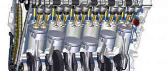
on Gazelles. The eight-valve engine has a lower camshaft and an overhead valve arrangement; its gas distribution mechanism contains the following parts:
- camshaft, it rotates in five supports of the cylinder block;
- camshaft, transmits movement from the crankshaft to the camshaft;
- 8 pushers, driven by camshaft cams;
- 8 aluminum rods;
- the rocker axis, on which the rocker arms themselves are located (8 pcs.) with adjusting screws;
- exhaust and intake valves located in the cylinder head.
When the camshaft rotates, the valves in the cylinder head rise and fall. Just like all other modern engines, the ZMZ-402 operates on a four-stroke circuit:
- first, an intake occurs into the internal combustion engine, the air-fuel mixture fills the cylinder;
- then the mixture is compressed in the cylinder, and it is ignited by a spark from the spark plug;
- working progress occurs;
- The last step in the process is the release of exhaust gases.
When compression occurs, both valves are closed and sealed - the valves are adjusted in this position. In order for the combustion chamber to be sealed at the moment of compression, there must be a thermal gap between the valve stem and the rocker arm - if there is none, when the metal expands on a hot engine, the valve will not fit tightly to the seat (seat), the engine may lose power, and in some cases In some cases, it will not start at all.
Adjustment of engine valves ZMZ 402 (ZMZ 410, ZMZ 511, ZMZ 5233)
The valves on the ZMZ-402 can be adjusted in two ways. In the first option, the adjustment is made as follows (let's take the GAZ 24 car as an example):
- stop the engine, turn off the ignition, put the car in neutral;
- open the hood, remove the air filter housing;
- remove the valve cover, it is held on by six bolts;
- crank the crankshaft, align the first cylinder with the marks. The mark is located on the front crankshaft pulley;
- It should be noted that the marks on the pulley may coincide at TDC (top dead center) of the 1st and 4th cylinders, and if the valves of the 1st cylinder are clamped while the valves of the fourth are free, then the marks coincide with the 4th cylinder , and not with the 1st. This can be easily checked - remove the distributor cover and look where the slider points;
- adjust both valves on the first cylinder (gap 0.3 mm), turn the engine half a turn clockwise (the marks should be at the bottom)
- adjust both valves on the second cylinder;
- turn it another half turn (the marks are again at the top and coincide), adjust the valves of cylinder 4;
- We make another half revolution of the crankshaft (the marks are again below) and make adjustments on the third cylinder.
Close the valve cover, start the engine and check how the engine works. Valve clearances on all GAZ vehicles are adjusted using special feeler gauges; they are usually collected in one set.
There is such a thing as valve overlap, and if the valves of the first cylinder (at TDC) are free, both valves of the 4th cylinder will be clamped, but on the second and third, one valve each will remain free. Therefore, the adjustment can be done in two crankshaft rotations:
- set the TDC of the first cylinder, adjust the valves 1-2-4-6, counting them from the front of the engine;
- make a revolution of the crankshaft and adjust all the other valves (3-5-7-8).
In the books, it is recommended to carry out the adjustment on the cold side, on the outer valves (1) and set the gap to 0.35 mm, on the rest - 0.3 mm. But the cold adjustment cannot be done - aluminum rods expand as the engine heats up, and the gaps in the valves on a hot internal combustion engine decrease. Practice has shown that the most optimal option is adjustment on a well-warmed-up engine with gaps of 0.3 mm on all valves. By the way, the valve clearances on the GAZ 21 Volga are adjusted in the same way.
Adjusting valves on a GAZELLE - the simplest method
The size of the gaps in the valve drive:
| Cylinder number | Valve | Gap size, mm |
| 1 | Inlet Outlet | 0,40 – 0,45 0,35 – 0,40 |
| 2 | Inlet Outlet | 0,40 – 0,45 0,40 – 0,45 |
| 3 | Inlet Outlet | 0,40 – 0,45 0,40 – 0,45 |
| 4 | Inlet Outlet | 0,40 – 0,45 0,35 – 0,40 |
Indications for major repairs
Actually, indications for major overhaul 2 are increased consumption of gasoline and/or oil. In principle, that’s all. Any malfunction of the engine (and not only, but also the chassis, for example) will one way or another lead to an increase in fuel consumption. At the same time, the car will not lose dynamics (well, unless everything is extremely neglected, like a burnt-out piston valve) . For any car, the manufacturer indicates the normal consumption of both gasoline and oil. In the case of the Volga with ZMZ 402, gasoline consumption in the city should be 13.8 liters per 100 km, and oil consumption should be no more than 250 grams per 100 km.
In my case, the consumption was 25-30 liters, but I had to add a liter of oil per month, with a mileage of less than 400 km. Gasoline consumption was measured using the odometer. As further developments of events showed, in addition to the wear of the engine itself, the increased consumption was also contributed by a slipping clutch and a jamming brake pad, as well as a muffled EPH system.
The capitalization was done a year ago, upon completion of the run-in, it turned out that in the winter during normal driving (without slipping) it was 20 liters, in the summer the consumption was 14-16 liters when driving with an average degree of aggressiveness. During the run-in, the problem of oil leaks was actively resolved and by the time the run-in was completed, the engine was switched to synthetics, which it still runs on.
Recommendations for action
The adjustment of the engine valve 402 is similar to other similar ones, since this device is not unique.
According to the technical documentation, namely the service manual, the clearances for the intake and exhaust valves should be 0.4 mm. If the GAZelle valves are adjusted, the 402 engine will be quite happy with this setting. Since the car is designed to transport heavy loads, this problem occurs quite often.
When adjusting the valves of a UAZ 402, the engine must be tuned to reduce fuel consumption, which means that the gaps should be at the level of 0.25-0.3 mm, which will also increase its throttle response.
If you are a fan of fast driving, driving in the mountains or off asphalt surfaces, gaps of 0.3-0.35 mm will be just right.
When using gasoline that is not suitable for the cylinder head (for example, using AI-80 on a cylinder head for AI-92), the gaps should be at the level of 0.4 mm.
Features of replacing the cylinder head gasket
With all the existing nuances of technology associated with the features of the engine design, type of gasket
or fastening bolts, there are general rules. Rules that are universal when replacing
gaskets
Cylinder head on any car.
We will not bore you with a detailed description of which bolt to turn in which direction. All the “tricks” for replacing the gasket are described in the manual specifically for your engine type. Read before you start repairing.
And, most importantly, you need to try to fulfill all the manufacturer’s requirements regarding assembly and disassembly cylinder head
.
- dismantling begins with a marker in hand. When disconnecting everything attached, especially pipelines, do not be lazy and do not rely on memory, mark everything. On our website you can get detailed information about the repair of UAZ 3163 (Patriot) Replacement of the cylinder head gasket. It will be easier to assemble.
- When purchasing a cylinder head gasket for replacement, do not forget to make sure that its properties are designed specifically for the torque force prescribed by the engine manufacturer for tightening the cylinder head bolts;
- Before you begin to unscrew the fastening bolts, you must thoroughly remove any oily deposits. Tearing the key off the slot threatens: injury to you or the bolt splines being torn off, and then you cannot do without drilling;
- We begin to unscrew the fastening bolts from the middle by 0.5 or 1 turn each. This is done in order to relieve tension;
- After you have removed the cylinder head and replaced the gasket, proceed to the reverse procedure. Installation block
head must occur strictly along the guide bushings, or along special grooves for alignment; - The cylinder head mounting bolts are tightened only using a torque wrench, according to the scheme defined by the manufacturer in the manual, and strictly according to the tightening torque parameters.
Replacing UMZ 4216 engines
If they purchase a Gazelle with an unsuccessful engine, car owners try to get rid of the power unit by replacing it with an internal combustion engine of another model. Many different options can be considered as a replacement, but most often owners of commercial vehicles install ZMZ-405 engines; this particular engine is chosen for a number of reasons:
- the Trans-Volga engine is not capricious - it “digests” Russian fuel well and does not break down often;
- relative to imported power units (Cummins, Toyota, Nissan), the ZMZ-405 is inexpensive;
- When installing the ZMZ, a minimum of rework is required.
Recently, Gazelle Business cars have been equipped with a Cummins turbodiesel as standard, but owners of cars with UMZ-4216 almost never consider this engine as a replacement:
- Cummins doesn't come cheap;
- The American engine is very sensitive to the quality of fuel, and if the car is fueled with bad diesel fuel, the Cummins can quickly fail.
Another advantage of the ZMZ-405 (or 406) is that many used engines in good working condition are sold on the secondary market, and their price is several times lower than a new internal combustion engine. True, when buying a used unit there are no serious guarantees - you have to take the seller’s word for it. Repair of UMZ 4216 engine; Replacing the cylinder head (gasket) Gazelle gasket. But even if the 405 requires minor repairs (replacing chains or piston rings), purchasing it along with repairs is still much cheaper than purchasing an expensive imported engine. Replacing the cylinder head gasket of a VAZ 2110. Another disadvantage of an imported internal combustion engine is that if it was not installed as standard on the Gazelle, you will have to purchase it together with the gearbox or be puzzled by the adjustment of mounting the Gazelle gearbox to the new engine.
Tightening torques for gazelle threaded connections
Attention! Experienced mechanics advise choosing the middle range from the data below. Since all torque wrenches have a small error.
There are only 10 bolts on the cylinder head of Gazelle engines. Their caps have a diameter of 14 mm. After all the bolts have been tightened, you need to go through them again to make sure that they are all tightened as needed.
On ZMZ 406 and 405 models, pulling the bolts of the device is carried out in the following steps:
- Stage one. The parts of the device are pulled using a torque wrench with a force of 40-60 Nm.
Stage two. The threaded parts of the device are pulled with a force of 127 - 142 Nm.
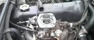
Removing the cylinder head of engines ZMZ-402, ZMZ-4021
Home — Engines — Removing the cylinder head of engines ZMZ-402, ZMZ-4021
The cylinder head can be removed with the intake pipe and exhaust manifold. If the cylinder head is removed from an engine installed on a car, you must first perform the following operations:
— drain the liquid from the cooling system; — remove the air filter from the carburetor; — disconnect the hoses from the thermostat; — disconnect the wire from the coolant temperature sensor; — disconnect the wires from the microswitch on the carburetor; — disconnect the choke rod and the accelerator drive rod from the carburetor; — disconnect the fuel drain hose from the carburetor; — disconnect the hoses from the EPHH solenoid valve installed on the bulkhead; — Disconnect the vacuum hose of the brake booster from the fitting on the intake pipe; — disconnect the heater outlet hose from the fitting on the rear cover of the cylinder head.
Further, the procedure for removing the cylinder head from an engine removed from a car and from one installed on a car is the same.
Table 2.7. Nominal dimensions and fit of mating parts of the cylinder head
| the name of detail | Nominal diameter, mm | Name of mating parts | Nominal diameter, mm |
| Valve guide | 17,0 +0,066 17,0 +0,047 | Cylinder head | 17,0 +0,025 17,0 -0,010 |
| Inlet valve | 9,0 -0,050 9,0 -0,075 | Guide sleeve | 9,0+0,022 |
| Exhaust valve | 9,0 -0,075 9,0 -0,090 | Guide sleeve | 9,0+0,022 |
| Intake valve seat | 49,0 +0,125 49,0 +0,100 | Block head | 49,0 +0,017 49,0 +0,010 |
| Exhaust valve seat | 42,0 +0,125 42,0 +0,100 | Block head | 42,0 +0,017 42,0 +0,010 |
| Valve rocker shaft | 22,0 -0,007 22,0 -0,021 | Rocker axle stand | 22,0 +0,030 22,0 +0,008 |
| Valve rocker shaft | 22,0 -0,007 22,0 -0,021 | Valve Rocker Bushing | 22,0 +0,028 22,0 +0,007 |
| Rocker bushing | 23,4 +0,07 23,4 +0,04 | Valve rocker arm | 23,25 +0,045 |
| Stub | 17,0 +0,115 17,0 +0,080 | Valve rocker shaft | 17,0 ±0,035 |
| the name of detail | Gap, mm | Preload, mm | ||
| min | max | min | max | |
| Valve guide | __ | __ | 0,022 | 0,076 |
| Inlet valve | 0,05 | 0,97 | __ | __ |
| Exhaust valve | 0,075 | 0,117 | __ | __ |
| Intake valve seat | __ | __ | 0,083 | 0,135 |
| Exhaust valve seat | __ | __ | 0,083 | 0,135 |
| Valve rocker shaft | 0,015 | 0,051 | __ | __ |
| Valve rocker shaft | 0,014 | 0,049 | __ | __ |
| Rocker bushing | __ | __ | 0,145 | 0,220 |
| Stub | __ | __ | 0,145 | 0,150 |
Inspection
1. After disassembling the cylinder head, wash all parts in gasoline, wipe and dry. Clean the combustion chambers from carbon deposits.
2. Inspect the block head. If there are cracks on the bridges between the valve seats or on the walls of the combustion chambers, or signs of burnout, replace the cylinder head.
3. Using a metal ruler and feeler gauges, check whether the flatness of the surface of the head adjacent to the block is broken.
To do this, place the ruler with its edge on the surface of the head, in the middle along, and then across, and use feeler gauges to measure the gap between the plane of the head and the ruler. If the gap exceeds 0.1 mm, replace the head.
4. Inspect the valves. If cracks, warping of the valve head, burnout, or deformation of the stem are detected on the working face of the valve, replace the valve. Minor marks and scratches on the working face of the valve can be removed by lapping.
5. Check the condition of the valve springs. Replace bent, broken or cracked springs.
6. Check the condition of the valve seats. There should be no signs of wear, holes, corrosion, etc. on the working chamfers of the seats. Minor damage (small marks, scratches, etc.) can be removed by grinding the valves.
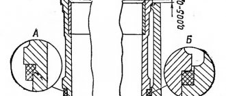
More significant defects can be removed by grinding. When grinding, maintain the seat dimensions indicated in the figure.
After grinding, check the runout of the seat chamfer relative to the hole in the valve guide; the maximum permissible runout is 0.05 mm.
After grinding the seats, grind the valves. Then thoroughly clean the block head and blow it with compressed air so that there are no abrasive particles left in the channels closed by the valves and in the combustion chambers.
7. Check the gap between the guide bushings and valves. The clearance is calculated as the difference between the diameter of the hole in the bushing and the diameter of the valve stem.
The maximum permissible gap is 0.25 mm. If the gap exceeds the specified value, the valve and guide sleeve must be replaced.
The old bushing is pressed out using a mandrel from the side of the combustion chamber. Before installation, new bushings must be cooled in carbon dioxide (“dry ice”), and the block head must be heated to 160 - 175 ° C.
Then insert the bushing into the cylinder head so that it protrudes from the valve spring side above the cylinder head by 20 mm. The bushing should fit into the head freely or with little force.
After installation, expand the hole in the bushing to a diameter of 9.0 +0.022 mm. Then grind the valve seat, centering the tool on the hole in the bushing.
8. You can check the block head for cracks as follows. Connect a compressed air hose to one of the holes in the cooling jacket.
Plug all holes in the block head with wooden plugs. Lower the head into a bath of water and apply compressed air at a pressure of 1.5 atm. Air bubbles will emerge where cracks form.
9. Clean with wire and blow out with compressed air the holes in the rocker arm axle, in the rocker arms and in the adjusting screws. Check the tightness of the bushings in the rocker arms.
If the bushing does not fit tightly, it needs to be replaced, since during engine operation it can turn and block the hole for supplying oil to the pusher rod.
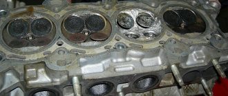
Valve seat profile for engines mod.
402 and 4021 :
A - intake valve seat;
B - exhaust valve seat
Engine mount
The engine is mounted on the chassis on three rubber mounts: two are located in the front of the engine (one on each side), one is located at the rear, under the gearbox extension
The front airbags are located obliquely in the transverse plane of the engine. The pillows have steel plates at the top and bottom. A bolt is screwed into the top plate, connecting the cushion to the bracket on the engine. The cushion is connected to the chassis bracket by two bolts embedded in the cushion fittings. The chassis brackets are screwed (each with two bolts) to the front suspension cross member. To strengthen the connection of the bolts with the cross member, conical split bushings are installed in the conical holes of the cross member, tightly enveloping the bolt when it is tightened. The rear cushion has steel plates at the bottom and top, in which two bolts are secured. The cushion is attached to the transmission extension platform and to the cross member. L-shaped limiter plates are installed between the pillow and the extension. Limiters prevent excessive movement of the engine in the longitudinal direction when braking and accelerating the vehicle. For proper operation of the limiters, it is necessary that the gap between the edge of the vertical surface and the surface of the cushion (at each limiter) be 3 mm. The gap is established by moving the cross member on the bolts, attaching it to the frame brackets.
While operating the vehicle, you should periodically check the condition of the engine mount parts, tighten bolts and nuts if necessary, and clean the cushions from dirt and oil that has fallen on them.
Assembly
Assemble the block head in the reverse order of disassembly. Before installation, lubricate oil seals, valve stems and valve rocker shafts with engine oil. Install the valves in accordance with the marks made during disassembly.
Install the gasket of the thermostat housing and the gasket of the rear cover of the block head with a Hermesil type sealant.
When installing the cylinder head, it is recommended to replace the cylinder head gasket.
The cylinder head is installed in the reverse order of removal. The procedure for tightening the cylinder head bolts is shown in Fig.
Sequence of tightening the cylinder head bolts. Tightening torque 83–90 N m (8.3–9.0 kgf m). After installing the cylinder head, adjust the clearances in the valve drive.
Comparison of cylinder head gaskets with triangular and round windows
So here they are:
The triangular one has an extra hole in the front and three extra holes in the area of the central studs; if you look at the cylinder head, you can see that corrosion occurs in the places where the extra holes are. Also, the triangular one is missing two holes at the back wall in the area of the tank. There is an opinion that with a triangular gasket, circulation worsens in the summer when the heater is closed in the area of the 4th cylinder, I did not notice this, but I admit that this is possible if you drive at low speeds of 1000-1500 in the heat. I have XX 1000 rpm, I try to drive at 2-3 thousand rpm.
However, when tightening, I specifically paid attention to the “creasability” of the gaskets. The triangular one sank noticeably, that is, with an increase in torque by 1 kg, it was possible to make more revolutions
In the case of the round one, I especially noticed that when pulling with a force of 10 kg after 9 kg, all the nuts turned less than 90 degrees, that is, the gasket wrinkles slightly, and this, as I understand it, indicates a high-quality gasket. Of course, there is a possibility that the previous triangular one turned out to be the left one, but I advise you to pay attention when tightening, if the gasket keeps being pulled and pulled, it won’t last long. Alternatively, this may be due to the fact that the triangular one is designed for a cast iron block with a different configuration of mating surfaces.
In general, I am now a supporter of gaskets with round windows, although time will tell. Again, from the point of view of throughput, I estimated, and it turned out that the total cross-section of the holes in the round gasket is no less than the cross-section of the thermostat or radiator pipes, that is, it will not limit the coolant circulation.
Removing the cylinder head
To remove the cylinder head, first remove the rocker arm axle, then carefully unscrew the 10 nuts. I had a couple of nuts that creaked, so I had to unscrew them smoothly. Important! To avoid distorting the cylinder head, the nuts must be unscrewed in the same order as when tightening, a little at a time.
That is, first we pull the nuts out of place. Then unscrew all the nuts sequentially, unscrewing them a third of a turn. Further, all hope is that there was no collective farm during the last installation of the cylinder head (such as stuck solid oil). However, even if there is no stuck gasket, there will most likely be a problem with the penultimate stud on the passenger side:
The reason, apparently, is that it is located between cylinders 3 and 4 and is subject to chronic overheating, and coolant flows there as a bonus. As a result, a very dense layer of oxide appears between the stud and the cylinder head. Moreover, it will not be possible to pull off the cylinder head with your hands without a tool. Since both the cylinder head and the block are made of aluminum, it is highly not recommended to use crowbars and other metal levers, since the mating surface may be damaged, which can lead to leaks. Through experience I came up with this scheme:
I made it from scrap materials, but this is the point - we take a metal corner, drill holes for the rocker arm axle studs, and between the rocker arm axle studs this corner rests on the cylinder head mounting stud, the penultimate one on the driver's side. Thus, by tightening the nuts of the rocker arm axle studs, the corner is pressed to the cylinder head, and due to resting against the stud, the cylinder head is slowly pulled upward. Thus, I managed to pull off the cylinder head halfway, then I used a crowbar, but I do not recommend doing this. It can be seen that the stud itself is relatively intact, that is, it was mainly aluminum that was oxidized:
To prevent the sleeves from moving, we fix them with bushings; wide 16 washers are used:
Tools and spare parts
My oil pressure up to the capital was satisfactory, so I didn’t plan to remove the crankshaft. I didn’t plan to change the earbuds either. From spare parts I took a set of valves:
New valve springs. It is necessary to change them when capitalized, Evgeniy Travnikov constantly repeats this, they say that tired valve springs waste power at high speeds. It seems to be true, after 3000 the engine with new springs began to pull much more fun.
Re-bushing was also planned, for which a set of bushings was purchased.
True, I previously bought 4 pieces individually for training in how to correctly unfold the bushings.
A set of gaskets was also purchased for the overhaul of ZMZ Golden Series. This set turned out to be a rare mess, so I advise you to buy separately oil seals, front crankshaft oil seal, crankcase cork gaskets, valve cover and pushrod covers. For all other gaskets, I advise you to buy oil- and petrol-resistant paronite and cut the necessary gaskets locally yourself.
The following tools will be required:
A 1/2 torque wrench and a 17 mm rim socket.
Valve grinding tool:
Lapping paste
Piston ring mandrel:
A mandrel for pressing on oil seals will not hurt:
A 9mm reamer is required:
The valve depressurizer will make life easier and save bushings:
One of the most expensive items is cutters:
I read a lot of horror stories about the hardness of the 402 head saddles, but I didn’t have any problems with these cones; it took no more than 2-3 minutes to make one saddle. True, I didn’t overdo it.
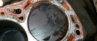
Washing of parts
The next stage of the overhaul is to wash the parts from resinous deposits. This is what the cylinder head looked like a year before the overhaul, after 1.5 years on semi-synthetics:
Washing was carried out with dishwashing detergent (any kind will do) using a toothbrush. The technology is as follows: we drip some dishwashing detergent and rub it with a toothbrush, until the slurry turns black, wipe it dry with a paper napkin. And so on, in this way almost all the details were washed:
I didn’t want to understand the rocker axis, I didn’t insist