Valve clearance UAZ 417 engine
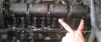
Everything is simple) 1. combine the mark on the crankshaft pulley with the mark on the block, I have one single hole in the pulley, or this is mark No. 1 TDC (facing the pulley, the mark will be on the left) mark No. 2 for adjusting the ignition.
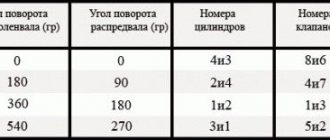
2. Remove the distributor cover, the slider should be located at the contact of the first cylinder (we look along the high-voltage wire going to cylinder 1) 3. adjust valves 1, 2, 4, 6, 4. rotate the knee 360 degrees and adjust 3, 5, 7, 8 valves (see which valves are closed, it is possible to replace points 1 and 2, then the slider will be turned to cylinder 4) (the first valve is on the pump) ATTENTION! PURCHASE A NEW VALVE COVER GASKET IN ADVANCE SO YOU DO NOT WASTE TIME! There is a more scientific method, but it takes much more time)))
The gas distribution mechanism requires periodic adjustment of the clearances between the rocker arms and valves, which should be performed on a cold engine after a run of 16,000 km or when signs of clearance violations appear (knock of valves, reduction in engine power, flashes in the carburetor, “shots” in the muffler) in the following order :
– install the piston of the first cylinder according to the mark on the crankshaft pulley to the top dead center. During the compression stroke, use a feeler gauge to check the gap between the rocker arms and the valves of the first cylinder. If the gap is incorrect, unscrew the lock nut of the adjusting screw and, turning the adjusting screw with a screwdriver, set the gap according to the feeler gauge, then, holding the adjusting screw with a screwdriver, tighten the lock nut and check again that the gaps are set correctly; – after adjusting the clearances of the next cylinder, turn the crankshaft half a turn and adjust the clearances for the remaining cylinders according to their operating order: 1–2–4–3. Gap between rocker arms and valves on a cold engine (at 15-20°): For exhaust valves of the 1st and 4th cylinders, mm ─ 0.30 – 0.35 For other valves, mm ─ 0.35 ─ 0.40 mm
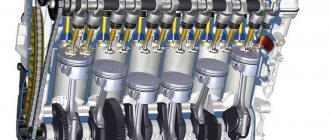
The gas distribution mechanism of the UMZ-417 engine includes a camshaft assembly, intake and exhaust valves, valve drive - pushrods, pushrods, rocker arms, valve springs.
The gas distribution mechanism of the UMZ-417 engine.
The intake and exhaust valves are located vertically in a row in the cylinder head. The valves are driven by the camshaft through pushrods, pushrods and rocker arms. The camshaft is made of steel, has five bearing journals, valve drive cams, an oil pump drive gear and a fuel pump drive eccentric.
The intake and exhaust cam profiles are not the same. The cams have a taper of 10-15′, this is done to impart rotation to the pushers. Since the outer surface of the bottom of the pusher is made spherical, and the cam is conical in width, the point of contact of the cam with the pusher is shifted relative to the axis of the pusher. This leads to constant rotation of the pushers when the engine is running, which ensures uniform wear of the parts.
The axial movement of the camshaft is limited by a steel thrust flange located between the end of the camshaft journal and the gear hub. The working gap of 0.1-0.2 mm between the gear hub and the thrust flange is ensured by the fact that the spacer ring clamped between the gear and the camshaft journal is thicker than the thrust flange. The correct distribution phases are ensured by installing the gear according to the marks. Mark 0 on the crankshaft gear should be against the groove of the tooth on the textolite gear.
Piston type pushers, steel, outer diameter 25 mm. The end of the pusher, resting on the cam, is coated with special bleached cast iron and processed into a sphere with a radius of 750 mm. The pushers are installed in the guide holes made directly in the block, with a gap of 0.015-0.040 mm.
The push rods are made of duralumin rod and have steel tips pressed onto both ends, the spherical surfaces of which are heat-treated. The valve rocker arms are cast steel and are the same for all valves. The long arm of the rocker ends with a heat-treated cylindrical surface resting on the end of the valve stem, the short arm ends with a threaded hole into which the adjusting screw is screwed.
The valves are overhead, located in the cylinder head. The exhaust valves are made of heat-resistant steel EP-303, and the intake valves are made of chrome steel 4Х9С2. The diameter of the intake and exhaust valve stems is 9 mm. The intake valve plate is tulip-shaped with a diameter of 44 mm, and the exhaust valve plate is flat, with a diameter of 36 mm. The ends of the valve stems, on which the rocker arms rest, are hardened along a length of 3-5 mm.
The valve spring is made of spring steel, the coil pitch is constant. The valve guides are cermet, made by pressing followed by sintering of a mixture of iron, copper and graphite powders. This bushing has high anti-friction qualities.
Maintenance of the gas distribution mechanism of the UMZ-417 engine.
Maintenance of the gas distribution mechanism of the UMZ-417 engine consists of cleaning the valves from carbon deposits and grinding them in. Adjustment of clearances is carried out as planned after one maintenance or when signs of their violation appear.
The gas distribution mechanism of the UMZ-417 engine needs to adjust the gaps between the rocker arms and valves when signs appear, expressed in the knocking of valves, a decrease in engine power, the appearance of flashes in the carburetor, and “shots” in the muffler. The gas distribution mechanism is checked and adjusted on a cold engine.
Checking and adjusting the gap between the rocker arms and the valves of the gas distribution mechanism of the UMZ-417 engine.
To check and adjust the clearance, it is necessary to remove the rocker cover, avoiding damage to its gasket. Set the piston of the first cylinder to the mark on the crankshaft pulley at top dead center during the compression stroke, and use a feeler gauge to check the gap between the rocker arms and the valves of the first cylinder.
If the gap is incorrect, unscrew the lock nut of the adjusting screw and, turning the adjusting screw with a screwdriver, set the gap according to the feeler gauge, then, supporting the adjusting screw with a screwdriver, tighten the lock nut and check that the gap is correct.
By turning the crankshaft half a turn each time after adjusting the clearances of the next cylinder, the clearances for the remaining cylinders are adjusted according to the order of their operation. The clearances for the exhaust valves of the first and fourth cylinders, valves 1 and 8, should be within 0.30-0.35 mm, for the remaining valves, within 0.35-0.40 mm.
Crank mechanism of the UAZ-469 engine
Details Category: UAZ-469 engine
Engine cylinder block made of aluminum alloy. The cylinders are made in the form of removable wet liners cast from gray cast iron. The upper part of the liner is sealed by clamping the liner collar between the block and the cylinder head through the gasket, and the lower part - through a rubber ring made of oil- and petrol-resistant rubber (Fig. 14). The cylinder head is made of aluminum alloy with insert seats and valve guides. Between the block and the head there is a gasket made of asbestos steel fabric, impregnated with graphite and reinforced with a metal frame. Gasket thickness (compressed) 1.5 mm. To avoid the gasket sticking to the block and head, it is rubbed on both sides with graphite powder before putting it in place. The gasket is symmetrical. The pistons are made of aluminum alloy with a thermostatic insert, tin-plated. There are three grooves in the upper part of the piston: the upper two grooves are used to install compression rings in them, and the lower one is for installing a composite oil scraper ring.
Rice. 14. Installing the liner into the cylinder: A - position of the rubber ring on the liner before pressing; B - position of the rubber ring when pressing the sleeve.
Pistons are selected to the cylinders (during engine assembly and repairs) with a gap of 0.012 ... 0.036 mm. Three piston rings are installed on each piston: two compression rings and one composite oil scraper ring. To increase wear resistance, the outer surface of the upper compression ring is coated with a thin layer of porous chrome. The outer surface of the second compression ring is coated with tin to improve running-in to the cylinder. The inner cylindrical surfaces of both compression rings have grooves, due to which the rings are slightly turned out after they are installed in the working position (Fig. 15). This improves and speeds up their running-in to the cylinders. The rings must be installed on the piston with the grooves upward, towards the bottom. The joints of the rings must be separated by 180° in relation to each other.
Rice. 15. Installation of rings on the UAZ-469 piston: 1 - piston; 2 — compression rings: 3 — annular disks; 4 - axial expander; 5 — radial expander; 6 — thermostatic insert
The oil scraper ring is made of steel, has two annular disks, radial and axial expanders. Two annular disks remove excess oil from the cylinder mirror, which is discharged into the engine crankcase through holes in the piston. The ring lock is straight. The piston pins are of a floating type, hollow. The piston pin is selected to the piston and the upper head of the connecting rod with minimal clearances acceptable under lubrication conditions. The connecting rods are steel I-section. Thin-walled tin bronze bushings are pressed into the upper heads of the connecting rods. To lubricate the piston pin, there is a hole in the upper head of the connecting rod that coincides with the hole in the bushing.
UAZ valve clearances
One of the main types of work is periodic adjustment of valves on UAZ 469, UAZ 417, UAZ 421, and also, if possible, cleaning them from carbon deposits.
The UAZ 469 valves on UMZ 421 and 402 are quite reliable in operation, since they are made of chromium steel, and when working on the exhaust valves, heat-resistant steel was used. To adjust the valves on the UAZ 469, like the UAZ 3303, including those with the 402 engine, it is necessary to check the gap between the valves and pushers at certain intervals. If the gaps are larger than normal, then it is more difficult to start the engine, and its operation is accompanied by knocking in the valves and a drop in power.
In the case of reduced valve clearances in the UAZ 469, problems occur in the carburetor, “coughing” and popping noises in the muffler, and the engine cannot develop maximum power. There is a problem with the carburetor (you can hear it). The gaps should be set in accordance with the standards on a cold engine during TO-2.
Adjustment without hydraulic compensators
Until 2009, the Gazelle car was equipped with the UMZ 4216 engine without hydraulic compensators, the design of the gas distribution mechanism is practically no different from the previously created UMZ 100 carburetor engine (popularly called “weaving”).
With the start of production of Gazelle business cars, the “weaving” engine was modernized, an injector was installed, and the “gasket” oil seal was replaced with a standard rubber one. In addition, with the installed catalyst, the car began to belong to the Euro-3 class. Adjustment of the thermal clearances of the UMZ 4216 valves is carried out according to the manufacturer’s instructions, similar to the technology performed on the Gazelle “weaving”.
The frequency of adjustment on internal combustion engines is recommended every 10,000 km. If the car is constantly serviced by one specialist who adjusts the gaps, then, according to his recommendation, the mileage interval between adjustments can be increased to 20,000 km.
The engine reminds the driver of the need to adjust the gaps by lack of traction characteristics, increased fuel consumption, or an excessively loud ringing clatter. An experienced specialist can already determine by the sounds of an idling engine the condition of the thermal gaps. A smoothly running engine with no quiet knocking sounds from the valves is a sign of a small clearance (“pinched” valve) and, conversely, a very loud knock indicates that the clearance is too large. In both cases, it is necessary to normalize the thermal gaps, since if the gap goes positive or negative during operation, the injection phase changes.
Features of setting TDC
When carrying out work on adjusting the UAZ 469 valves on the 402 engine, one of the main points is the correct setting of TDC (top dead center) in compliance with the further algorithm, following which we will carry out the work quite quickly. One of the main tools for working with valves is a 0.3...0.35 feeler gauge.
When adjusting valves on UAZ 469 and UAZ 3303 with engines 402, 417 and 421, you should know that they do this in cylinder order 1-2-4-3. Although in some cases it may be violated. Accordingly, in this order it is necessary to adjust both the intake and exhaust valves on each cylinder.
To begin with, we inspect the distributor cover, fix the place of the slider for the spark to exit to the spark plug of the first cylinder and find the wire going to this spark plug. In this case, the distributor on top should, by analogy with the hands of a clock, show 10-00. After this, completing the adjustment of the valves on the UAZ 469, remove the valve cover and disconnect all the attachments.
The gap is measured with a feeler gauge
The next step is to inspect the crankshaft pulley. There should be two or three lines on it. We find them and combine the last line on the right in the direction of rotation with the guide on the cylinder block. We insert the “crooked starter” and connect the indicated line with the guide. If it is not possible to use it, then you should rotate the shaft manually. It is important to remember that if we are facing the engine, the direction of rotation of the valve pulley on the UAZ 469 will be clockwise.
After this we study the distributor slider. If it is in the right place, this means that the piston of the 1st cylinder is located at TDC. The valves are closed at this moment, so we can safely adjust them. You should press the rocker arm where the gap should be felt.
Next, take the feeler gauge and set the gap to 0.35 mm. In this case, a slight force must be made to insert the probe. We insert the dipstick into the gap between the valve and the rocker arm. Having loosened the lock nut, we turn the adjusting bolt left and right, depending on the need to increase or decrease the gap. It is advisable that the gap be set to 0.35 on the valves of all cylinders. If the air temperature is below 0 (up to -5), then a gap must be made. Let's see how well we adjusted the valves on the UAZ 469, either according to the distributor slider, or according to the notch on the pulley. Next, turn another 180° again and continue adjusting the fourth cylinder. Finally, repeating the same 180 o, we finish the third. The final stage of valve adjustment on the UAZ 469 is the installation of the valve cover with the connection of equipment to it.
In any condition of the machine on UMZ 421 and 402 it is necessary to tighten the cylinder fastening nuts every 1000 km.
The quantity screw usually specifies the speed (they are 100-200 revolutions higher than normal). And by turning the quality screw 1/4 or 1/2, we reduce the speed. This allows you to keep the CO level within 1-2%.
Currently, the Ulyanovsk plant produces the UAZ 3303, which is also equipped with a 417 m petrol engine with a volume of 2.445 liters and 40,000 rpm. The operating order of the valves on the UAZ 3303 is the same as the 1-2-4-3 we reviewed.
How to adjust the valves of the UMZ 421 engine. Video
The UMZ 421 engine is well known to UAZ drivers. Experienced car enthusiasts know that one of the main “items” of periodic maintenance of Ulyanovsk SUVs is valve adjustment. These parts are made of chrome steel, so they are highly reliable. Diagnostics of the valves is simply necessary, because if the gap exceeds the norm, then the engine starts hard and “knocks”, and its power drops. A smaller gap leads to the appearance of characteristic pops in the muffler, and the carburetor begins to malfunction. How to adjust the valves of the UMZ 421 engine is described in the video and in this manual:
Engines of the “421” family (as well as the proven “four hundred and two”) require quite frequent tightening of the cylinder fasteners. “Ideally” this should be done every thousand kilometers, although many question this norm. The repair process is shown in the video presented here on how to adjust the valves of the UMZ 421 engine with your own hands.
Timing belt and engine valves UMZ-421, UMZ-4218 for UAZ-Hunter, UAZ-31512, UAZ-3303, 2206
Gas pipeline of the engine UMZ-421 (UAZ-31512), UMZ-4218 (UAZ-Hunter, UAZ-3303, 2206) Gas pipeline UMZ-421, UMZ-4218 (see Fig. 1/2) consists of an aluminum inlet pipe and a cast iron outlet collector The intake pipe and exhaust manifold are connected to each other into one unit through a gasket with four M8 studs, and their plane of contact with the cylinder head is processed as an assembly with a non-flatness of no more than 0.15 mm, so disassembling the unit unnecessarily is undesirable. Rice. 1. Gas pipeline of UMZ-4218 engines for an untuned exhaust system 1 – intake pipe; 2 – exhaust manifold; 3 – “winter-summer” damper for heating the intake pipe; 4 – flange for connecting the exhaust pipe of the muffler. On the UMZ-421, UMZ-4218 engines, three main modifications of gas pipelines are used, which differ from each other in manifolds - for a tuned and untuned exhaust system and inlet pipes - with a flange for installing a recirculation valve and without it. A gas pipeline with a manifold for a customized exhaust system with an intake pipe without a seat for the recirculation system valve is used on UMZ-421 engines Fig. 2. Gas pipeline of the UMZ-421 engine for a customized exhaust gas system: a - for engines without an exhaust gas recirculation system, b - for engines with an exhaust gas recirculation system. 1 – flange for installing the recirculation valve; 2 – flange for connecting the exhaust pipe of the muffler. The gas pipeline for the exhaust system without adjustment and the intake pipe without a socket for the recirculation valve are installed on all versions of UMZ-4218 engines. Gas pipeline designation – 417.1008010-20. Figures 1 and 2 show the characteristic differences of all the gas pipelines mentioned above. The middle part of the intake pipe is heated by exhaust gases passing through the intake manifold. The degree of heating can be adjusted manually using rotating damper 3 depending on the season. When the sector is rotated to a position in which the “winter” mark is opposite the locking pin, the heating of the mixture is greatest; when turning to the “summer” position, the heating is the smallest. Camshaft of the UMZ-421, UMZ-4218 engines On the UMZ-421 (UAZ-31512), UMZ-4218 (UAZ-Hunter, UAZ-3303, 2206) engines, two types of camshafts were used, which differ only in the material and technology of their manufacture. In terms of basic geometric dimensions and other parameters, they are practically unified. All engines starting from 2001 use only cast iron camshafts with the cams and fuel pump drive eccentric blasted to high hardness. The oil pump drive gear is steel, high-frequency hardened. On engines manufactured before 2001, either cast iron shafts or forged ones made of 45 Select steel with high-frequency hardening of the cams, fuel pump drive eccentric, oil pump drive gear and all support journals can be installed. Main parameters of camshafts UMZ-421, UMZ-4218 for UAZ-Hunter, UAZ-31512, UAZ-3303, 2206 (mm) Neck diameter: - first - 52-0.02 - second - 51-0.02 - third - 50-0.02 - fourth - 49-0.02 - fifth - 48-0.02 Runout of the third journal relative to the first and fifth journals - 0.02 Diameter of the front end of the shaft (for installation of the camshaft gear) - 28 Runout of the front end of the camshaft shaft UMZ-421, UMZ-4218 relative to the surface of the first and fifth journals - 0.025 Valve lift height 10.5 mm. The UMZ-421, UMZ-4218 camshaft is cast iron, cast with a steel drive gear for the oil pump and ignition distributor; has five support journals of different diameters (for ease of assembly): the first is 52mm, the second is 51mm, the third is 50mm, the fourth is 49mm, the fifth is 48mm. The camshaft journals UMZ-421, UMZ-4218 rest directly on the surface of the holes in the aluminum cylinder block. The working surface of the cams and the eccentric of the fuel pump drive is whitened to high hardness when casting the camshaft. The oil pump drive gear teeth are hardened. The intake and exhaust cam profiles are different. The width of the cams is ground to a cone. The conical surface of the cams, in combination with the spherical end of the pusher, imparts a rotational movement to the pusher when the engine is running. As a result, wear on the pusher guide and its end becomes uniform and small. Fig.3. – Camshaft UMZ-421, UMZ-4218 The camshaft UMZ-421, UMZ-4218 (Fig. 3) is driven into rotation from the crankshaft by helical gear 1. There is a cast iron gear with 28 teeth on the crankshaft, and a polyamide gear on the camshaft with 56 teeth. The use of polyamide ensures quiet operation of the gears. Both gears have two holes with M8x1.25 threads for a puller. The camshaft UMZ-421 (UAZ-31512), UMZ-4218 (UAZ-Hunter, UAZ-3303, 2206) rotates 2 times slower than the crankshaft. The camshaft is held against axial movements by a thrust steel flange 2, which is located between the end of the shaft journal and the gear hub with a gap of 0.1-0.2 mm. The axial clearance is provided by spacer ring 3, clamped between the gear and the shaft journal. To improve running-in, the surfaces of the thrust flange are phosphated. The gear is secured to the camshaft using a washer and a bolt with M12x1.25 thread. The bolt is screwed into the end of the shaft. Fig.4. Installation marks on the camshaft gears UMZ-421, UMZ-421 8 a - marks On the crankshaft gear, a mark “0” is applied against one of the teeth, and a mark or drilling is applied against the corresponding cavity of the camshaft gear. When installing the camshaft, these marks must be aligned (Fig. 4). Timing parts of the UMZ-421, UMZ-4218 engines of UAZ-Hunter, UAZ-31512, UAZ-3303, 2206 engines. The camshaft gear of the UMZ-421, UMZ-4218 (see Fig. 3) is helical, made of polyamide, reinforced with fiberglass. Compared to the previously used PCB gear, the polyamide gear makes less noise during operation and is less sensitive to fluctuations in the meshing clearance with the crankshaft gear. The gear has 56 teeth. The gear hub is made of ductile iron. Valve pushers UMZ-421 (UAZ-31512), UMZ-4218 (UAZ-Hunter, UAZ-3303, 2206) are steel, piston type. The end of the pusher is overlaid with bleached cast iron and ground to a sphere with a radius of 750 mm (the convexity of the middle of the end is 0.11 mm). Inside the pusher there is a spherical recess with a radius of 8.73 mm for the lower end of the rod. Near the bottom end, two holes are made to drain oil from the internal cavity of the pusher. The valve tappets of the UMZ-421, UMZ-4218 engines are divided into two size groups according to their outer diameter and the holes for the pushers in the cylinder block. When assembling, pushers of a certain group should be installed in the holes marked with the corresponding number. To ensure stability of the clearances in the valve mechanism of UMZ-421, UMZ-4218 during heating and cooling of the engine, the pusher rods are made of duralumin rod. Hardened steel tips with spherical ends are pressed onto the ends of the rods. The lower tip, mating with the pusher, has an end with a spherical radius of 8.73 mm, and the upper one, which fits into the recess in the rocker arm adjusting screw, has a 3.5 mm radius. The rod length of an engine with a compression ratio of 8.2 is 283 mm, an engine with a compression ratio of 7.0 is 287 mm. The rocker arms of the UMZ-421, UMZ-4218 valves (Fig. 5) are the same for all valves, cast steel. A bushing made of sheet tin bronze is pressed into the hole in the rocker arm hub. A groove is made on the inner surface of the bushing to distribute oil evenly over the entire surface and to supply it to the hole in the short arm of the rocker arm. Rice. 5. Valve drive of the UMZ-421, UMZ-4218 engine 1 – valve seat; 2 – valve; 3 – oil deflector cap; 4 and 5 – springs; 6 – spring plate; 7 – cracker; 8 – rocker arm; 9 – adjusting screw; 10 – adjusting screw nut; 11 – rod; 12 – spring support washer The long arm of the rocker arm ends with a hardened cylindrical surface resting on the end of valve 2, and the short arm ends with a threaded hole for the adjusting screw 9. The adjusting screw 9 has a hexagonal head with a spherical recess for the rod, and at the upper end there is a slot for a screwdriver . The spherical recess is connected by drilled channels with a groove on the threaded part of the screw. The groove on the screw is located opposite the hole in the rocker arm, i.e. approximately in the middle of the height of the threaded boss of the short arm of the rocker arm. In this case, the oil passes freely from the rocker channel into the screw channel. The adjusting screw is locked with locknut 10. The rocker arms of the UMZ-421, UMZ-4218 valves are mounted on a hollow steel axis, which is fixed to the cylinder head using four main struts made of high-strength or ductile cast iron and two additional struts made of ductile cast iron and pins passed through the struts. The fourth main strut on the plane adjacent to the cylinder head has a groove through which oil is supplied from the channel in the head into the cavity of the rocker arm axis. The remaining racks do not have a milled groove, so they cannot be installed in place of the fourth rack. The rocker arms are kept from axial movement by spacer springs that press the rocker arms to the racks. The outer rocker arms are located between the additional and main pillars. To increase wear resistance, the surface of the axle in the places where the rocker arms are installed is hardened. There is a hole for lubrication under each rocker arm in the axle. Engine valves UMZ-421, UMZ-4218 Valves UMZ-421, UMZ-4218 for UAZ-Hunter, UAZ-31512, UAZ-3303, 2206 vehicles are made of heat-resistant steel: the inlet valve is made of chromium-silicon steel, the exhaust valve is made of chromium-nickel-manganese with nitriding. A heat-resistant chromium-nickel alloy is additionally fused onto the working chamfer of the exhaust valve. Valve stem diameter 9 mm. The intake valve plate of UMZ-421, UMZ-4218 has a diameter of 47 mm, and the exhaust valve has a diameter of 39 mm. The operating chamfer angle of both valves is 45 degrees. At the end of the valve stem there is a recess for the valve spring plate crackers. The valve spring plates 6 (see Fig. 5) and the crackers 7 are made of steel and subjected to surface hardening. Rice. 6. Adjusting the gap between the rocker arm and the valve UMZ-421, UMZ-4218 1 – spring plate; 2 – valve; 3 – rocker arm; 4 – adjusting screw; 5 – lock nut For each valve UMZ-421, UMZ-4218, two springs are installed: an outer 4 with variable pitch with left winding and an inner 5 with right winding. The springs are made of heat-treated high-strength wire and shot blasted. Steel washers 12 are installed under the springs. The outer spring is installed downward with the end having a smaller pitch of turns. Valves UMZ-421, UMZ-4218 operate in metal-ceramic guide bushings. The bushings are made by pressing followed by sintering from a mixture of iron, copper and graphite powders with the addition of molybdenum disulfide to increase wear resistance. The inner hole of the bushings is finally processed after they are pressed into the head. The intake valve bushing is equipped with a retaining ring that prevents spontaneous movement of the bushing in the head. To reduce the amount of oil sucked through the gaps between the bushing and the valve stem, oil reflective caps 3 made of oil-resistant rubber are pressed onto the upper ends of all bushings. The distribution mechanism is closed on top with a rocker cover stamped from sheet steel. The rocker cover is secured through a rubber gasket to the cylinder head with six M6 bolts.
Adjusting UAZ valves
The frequency with which it is necessary to adjust valves on UAZ vehicles is 30-40 thousand kilometers. After adjustment work, the engine begins to operate more evenly and throttle response increases. This is due to the fact that the valve opening period increases, the supply of fuel to the combustion chamber and exhaust gas emissions becomes uniform in all cylinders, the resistance with which fuel enters the combustion chamber decreases, this increases the efficiency of the engine, which naturally affects the increase in power .
The gaps between the valve stem and the rocker arm should be 0.35 mm on intake valves and 0.40 mm on exhaust valves. The adjustment is made on a cold engine.
To adjust the valves, we start from the first cylinder; to do this, we set the piston in the top dead center position at the moment of fuel compression in the combustion chamber. What is the most convenient way to determine this position? There is a mark on the generator and pump drive pulley located on the crankshaft that must be aligned with the pin located on the front engine cover. But this is not enough, since this position also corresponds to the piston being at TDC at the moment of exhaust gas emission. Therefore, you can decide by the distributor; the slider should be located under the contact of the wire of the first cylinder.
Adjusting valves UAZ 469
We are glad to share with you another article from our website:
The UAZ 469 is equipped with a four-stroke, four-cylinder engine, the gas distribution mechanism of which includes 8 valves, rocker arms, a camshaft and pushers. When the power plant heats up to operating temperature, timing parts expand. To avoid deformation of parts, a temperature gap is established between the valves and pushers. It ensures the unhindered supply of the fuel mixture and the emission of exhaust gases from the combustion chamber, regardless of the temperature of the power plant.
Malfunctions
| FAULTS | CAUSES |
| Knocking and noise when the engine is running. | 1. The thermal clearances of the valves of the gas distribution mechanism (GRM) are not adjusted. 2. Defects in connecting rod bearings. 3. The timing camshaft is faulty. |
| Motor vibration. | 1. Imbalance of the crank mechanism. 2. Carburetor is not adjusted. 3. Ignition system defect. |
| Engine overheating. | 1. The thermostat is faulty. 2. An air lock has formed in the cooling system. 3. Defective water pump (“pump”). |
| Increased engine oil consumption. | Leaking through the rear oil seal packing (rope impregnated with graphite lubricant). |
The procedure for adjusting the valves of UAZ 469
Before adjusting the valves on the UAZ 469, you need to prepare the tools. To carry out the procedure, you will need a screwdriver, wrenches and a set of probes. To make adjustments, you do not need to place the car on an inspection hole or overpass. Work is carried out on a cold engine. Failure to comply with this rule may lead to increased noise and incorrect operation of the engine.
Adjusting valves on the UAZ 469 does not require specialized education. The work can be performed by a person with minimal technical knowledge. Adjustment is carried out in the following order:
- The attachments that prevent the removal of the valve cover are dismantled.
- The valve cover securing nuts are unscrewed. For convenience, you can use a socket wrench.
- The gasket that prevents oil leakage between the cylinder head and the valve cover is removed. When reassembling, it is better to replace the gasket with a new one.
- The piston of the first cylinder is set to top dead center. To determine the correct location of the piston, it is necessary to align the marks located on the crankshaft pulley and the front cover of the power plant. When the piston moves to top dead center, both valves of the gas distribution mechanism will be closed.
- The nut securing the adjusting screw located in the rocker arm above the pusher is unscrewed.
- A feeler gauge is installed between the rocker arm and the valve stem.
- The adjusting screw sets the required gap. The probe should pass between the parts with little effort. Biting the measuring element with timing parts is unacceptable.
- The adjusting screw is secured with a lock nut.
- The crankshaft rotates 180 degrees in the direction of travel.
- Manipulations are carried out on the next cylinder in turn. To adjust each subsequent cylinder, the crankshaft is rotated 180 degrees. The procedure for adjusting the valves on the UAZ 469 is 1-2-4-3.
The power unit is assembled in the reverse order. After adjustment, the engine runs less noisily, dynamic performance increases, and fuel consumption decreases.
Let's move on to adjusting the valves. Method one - by pulley
It is necessary to adjust the first, second, fourth and sixth valve, here we can see the gaps that will need to be adjusted. On the axis of the rocker arms you can see the so-called cog, which actually makes adjustments. This can be done with a screwdriver or an 11 wrench, which is more recommended. So, we take a 0.35 feeler gauge and place it in the gap between the axis and the top of the valve, right there we can observe play, or in other words, a broken gap that needs to be removed. To remove the backlash, you need a 14 wrench, which you need to loosen the lock nut, additionally holding it with a 11 wrench. After loosening the lock nut, we remove the gap using a 11 wrench. All movements must be performed slowly and carefully.
At the beginning, we said that adjustment is not a complicated process, but a tedious one. What is the tediousness of this process? And it lies in the fact that when we start to tighten the locknut back, it will pull the adjusting pin upward, which will lead to a gap forming again. For everything to go as expected, you will have to be patient and achieve the desired result. The probe should move a little stiffly, but it should pass. In general, to set everything up as needed, you will have to unscrew and tighten the locknut more than once. In the future, with experience and practice, it will be easier to adjust the valves, but a beginner will have to “sweat.” Next, we adjust the remaining valves in the same way as the first ones.
After we have completed the adjustment of the first, second, fourth and sixth valve, we need to adjust the remaining valves, that is, the third, fifth, seventh and eighth. To do this, you need to release them by turning the crankshaft 360 degrees again. Next, we adjust them according to the scheme known to us. This completes the valve adjustment on the 421 engine. Finally, we clean the valve cover, change the gasket, and put everything back together.
UAZ valve clearances
To improve the dynamic performance of the power plant of the UAZ 469 car, it is necessary to set the thermal gap on the intake valves to 0.35 mm, and on the intake valves - 0.4 mm. A discrepancy of indicators to a lesser extent can lead to damage to parts of the gas distribution mechanism. The valve will open too much. The piston rising to top dead center can bend the valve stem or tappet. Deviation of the gap to a larger direction will lead to a deterioration in the performance of the power unit.
IMPORTANT: Before adjusting the valves on the UAZ 469, you need to check that the rocker arms are securely attached to the cylinder head. If the fastening nuts are unscrewed, it will not be possible to adjust the temperature gap.
Features of setting TDC
The piston of each cylinder moves to top dead center twice in one cycle - at the moment of compression and during exhaust gas emission. In order to correctly set the thermal gap, it is necessary to set the piston of the first cylinder to top dead center at the moment of compression of the working mixture. You can do this in three ways:
- Visually determine the degree of valve opening. At the moment of compression, the cylinder valves are in a closed state. There is a small gap between the rocker arm and the valve stem. When exhaust gases are released, the exhaust valve is open. In this case, the rocker arm presses on the valve stem.
- Determine which cylinder receives a spark from the ignition distributor. To do this, it is necessary to remove the distributor cover and turn the crankshaft until the current-carrying contact of the slider turns towards the wire leading to the spark plug of the first cylinder
- Use a stub. The spark plug is removed from the first cylinder. A plug is made from paper, the diameter of which matches the seat of the candle. In order for the paper to cover the hole more tightly, the cork is moistened with water. After installing the plug in the spark plug seat, the crankshaft is rotated in the direction of travel. At the moment of compression, both valves close and the plug shoots out of the cylinder. Having heard a characteristic pop, it is necessary to stop the rotation of the crankshaft. Next, align the mark on the pulley and the front cover of the power plant.
Tuning
Increase the power of ZMZ 410 to 120 hp. With. simple enough. Almost every car enthusiast can cope with this by performing a number of simple operations:
If possible, you can increase the compression ratio in the engine cylinders. To do this, by milling it is necessary to bring the height of the cylinder head to 93 mm.
Further improvement of the technical characteristics of the motor is impractical for economic reasons. Installing a turbine or compressor will require switching to a fuel injection system, as well as replacing the connecting rod and piston group, crankshaft and other parts. The cost will be significantly higher than the price of the car.
Source
Adjusting UAZ engine valves
Adjusting thermal clearances in valve actuators
We check and adjust the clearances on a cold engine (15–20° C).
SEQUENCE OF ACTIONS Remove the cylinder head cover.
Using the starting handle, we turn the crankshaft by the ratchet bolt securing the damper pulley clockwise...
...until the third (clockwise) mark on the damper pulley aligns with the boss on the timing gear cover. At the end of the compression stroke of the first cylinder (both valves of the first cylinder are closed - when rocker arms are rocked, a gap will be felt between the rocker arms and the valves of this cylinder). Use a feeler gauge to check the thermal gap between the valve and the rocker arm*. With a normal gap, the feeler gauge should be able to move within it with little resistance. If the gap does not meet the standard, we adjust it. To do this......use a 14mm wrench to loosen the locknut of the adjusting screw. Using a slotted screwdriver, unscrew the adjusting screw 1–2 turns. Insert a feeler gauge of the required thickness between the valve stem and the rocker arm. We tighten the adjusting screw until the play between the rocker arm and the valve stem disappears. While holding the adjusting screw from turning with a screwdriver, we tighten the lock nut with a wrench (the gap will change slightly). And check the gap again.
If necessary, repeat the adjustment. We adjust the clearances of both valves of the first cylinder. We adjust the valve clearances of the second and remaining cylinders in the order 1-2-4-3, turning the crankshaft with the starting handle 180° each time.
* The clearances for the exhaust valves of the first and fourth cylinders (valves No. 1 and should be within 0.30–0.35 mm, and for the remaining valves within 0.35–0.40.
How to adjust valves on a 421 engine
The UMZ 421 engine is well known to UAZ drivers. Experienced car enthusiasts know that one of the main “items” of periodic maintenance of Ulyanovsk SUVs is valve adjustment. These parts are made of chrome steel, so they are highly reliable. Diagnostics of the valves is simply necessary, because if the gap exceeds the norm, then the engine starts hard and “knocks”, and its power drops. A smaller gap leads to the appearance of characteristic pops in the muffler, and the carburetor begins to malfunction. How to adjust the valves of the UMZ 421 engine is described in the video and in this manual:
Engines of the “421” family (as well as the proven “four hundred and two”) require quite frequent tightening of the cylinder fasteners. “Ideally” this should be done every thousand kilometers, although many question this norm. The repair process is shown in the video presented here on how to adjust the valves of the UMZ 421 engine with your own hands.
Engine UMZ-421. Guide - part 27
- check and, if necessary, adjust the fuel level in the float chamber, if
in this case, the float should rotate freely on its axis without touching the walls of the chamber;
— tighten screws 47 (Fig. 4.28) securing the accelerator pump cover, press the lever
drive 23 until it stops, tighten the screws and release the lever;
— tighten two screws securing the cover 36 of the EPHH valve, pull out the locking element 33
EPHH valve for size 13.5
mm from plane A (see “EPHH valve” assembly in Fig. 38),
tighten the mentioned screws, screw the economizer valve assembly 31 to the housing of the mixing chambers with two screws;
— when assembling, do not mix up the jets; - check the gap between the wall of the mixing chamber and the edge of the throttle valve when
fully open throttle valve of the primary chamber. The gap must be at least 14.5 mm. If necessary, provide clearance by bending the lever stop.
The durability and reliability of the repaired UMZ-421 engine largely depends on its adjustment after assembly, running in cold and hot modes and the mode of its operation in the car during the first thousand kilometers after repair.
Adjustment of valve clearances, cold and hot running-in of the UMZ-421 engine after repair.
After assembling the UMZ-421 engine, it is necessary to adjust the gaps between the valves and rocker arms and set the ignition timing. The gap between the valve and the rocker arm should be: for the intake valves of the 1st and 4th cylinders - 0.3-0.35 mm, for other valves 0.35-0.4 mm.
Adjusting the valve clearances of the UMZ-421 engine.
Set the piston of the first cylinder to TDC during the compression stroke, while the second mark on the crankshaft damper pulley in the direction of rotation of the crankshaft should align with the pin mark on the camshaft cover.
Using a feeler gauge, set the gap between the rocker arms and valves 1, 2, 4, 6 and tighten the locknuts of the adjusting bolts. Rotate the crankshaft one turn and adjust the clearances between the rocker arms and valves 3, 5, 7, 8.
Setting the ignition timing of the UMZ-421 engine.
Position the piston of the first cylinder near TDC during the compression stroke so that the first mark on the crankshaft damper pulley aligns with the pin on the timing gear cover.
Loosen the bolt securing the octane corrector plate to the ignition distributor sensor housing, with the cover removed, install the slider against the contact marked “1” on the distributor cover and insert the distributor shank into the hole in the drive housing, while the distributor coupling pin should fit into the groove of the drive sleeve.
The essence of the
Reliability and life expectancy of the engine greatly depend on valve adjustment. Despite the fact that the work is quite reliable, adjustment of the UAZ valves should be carried out after every 5 thousand km or when the size of the gaps between the rocker arms and valves changes, which manifests itself in valve knocking, a decrease in the performance of the power unit, “shooting” in the muffler, etc.
Technical nuances and adjustment procedure
According to the technical documentation provided by the Ulyanovsk Automobile Plant, the gaps should be: for the exhaust valves of cylinders No. 1 and No. 4 - 0.3-0.35 mm, for the remaining ones - 0.35-0.40 mm.
It is worth noting that the procedure for adjusting the UAZ valves is carried out in accordance with the operation of the cylinders, namely 1-2-4-3. In this case, it does not matter whether the injection or carburetor is being adjusted - the operations are performed in a similar way. The action itself is performed when the engine has cooled down.
Tools required: a set of feeler gauges, a standard driver's tool kit. Upon completion of the operation, the valve cover gasket is replaced.
Engine Specifications
UMZ engines are largely similar to engines produced by the Zavolzhsky Motor Plant. This is not strange, since the Ulyanovsk plant is part of GAZ OJSC. Over the entire period of production, many worthy engines were produced that deserved love and respect.
Let's consider the main motors produced by UMP, as well as their technical characteristics:
UMZ-417
| Name | Index |
| Manufacturer | UMP |
| Volume | 2.5 liters (2445 cm3) |
| Number of cylinders | 4 |
| Number of valves | 8 |
| Engine type | Petrol |
| Injection system | Carburetor |
| Power | 92 hp |
| Fuel consumption | 10.6 l/100 km |
| Cylinder diameter | 92 mm |
| Cylinder operating order | 1-3-4-2 |
| Econorm | Euro 4 |
According to the manufacturer's standards, the resource of the power unit is 150,000 km. While ZMZ analogues had a service life of 200-250 thousand kilometers.
UMZ-421
| Name | Description of characteristics |
| Model | UMZ 421 |
| Type | Carburetor/injector |
| Number of cylinders | 4 |
| Number of valves | 8 |
| Volume | 2.9 liters (2890 cc) |
| Cylinder diameter | 100 mm |
| Power | 98 hp in the carburetor version and 125 hp. — in the injector |
| Econorms | From Euro-0 to Euro-4 |
| Consumption | 11 liters per 100 km |
| The amount of oil in the internal combustion engine | 5.8 liters |
| Resource | 250+ thousand km |
| Oils that flow | 5W-30, 5W-40, 10W-30, 10W-40, 15W-40, 20W-40 |
The technical characteristics that the 421 engine received were high, and the engine itself became known as high-quality and reliable. The UMZ 421 was produced in two versions: carburetor and injector. Apart from these differences, the engine did not receive any other design changes.
Modifications of the UMZ 421 engine:
- UMZ 4218.10 - main engine, SZh 7 for 76 gasoline. Power 98 hp Compliance with environmental requirements Euro-1. Used on UAZ vehicles.
- UMZ 4218.10-10 - analogue of UMZ 4218.10, increased coolant to 8.2 for 92 gasoline. Power 103 hp Used on UAZ commercial vehicles.
- UMZ 421.10 is an analogue of UMZ 4218.10. The exhaust system has been changed. Used on UAZ vehicles.
- UMZ 421.10-30 is an analogue of UMZ 4218.10-10. The exhaust system has been changed. Used on UAZ vehicles.
- UMZ 4213.10-40 - analogue of UMZ-421.10-30, injector. Compliance with environmental requirements Euro-3. Power 117 hp Used on SUVs.
- UMZ 4213.10-50 is an analogue of UMZ-4213.10-40. Used on trucks.
- UMZ 4215.10-10 is an analogue of UMZ-4218.10. Used on Gazelle cars.
- UMZ 4215.10-30 is an analogue of UMZ-4218.10-10. Used on Gazelle cars.
- UMZ 4216.10 - analogue of UMZ 40215.10-30, injector, increased coolant to 8.8 for 92 gasoline. Power 123 hp Compliance with environmental requirements Euro-3. Used on Gazelle cars.
- UMZ 42161.10 is an analogue of UMZ 4216.10. Power 99 hp Used on Gazelle-Economy cars.
- UMZ 42164.10 - analogue of UMZ 4216.10, different camshaft. Compliance with environmental requirements Euro-4. Power 125 hp Used on Gazelle cars.
- UMZ 421647.10 - analogue of UMZ 42164.10, gas-gasoline. Power 100 hp Used on Gazelle cars.
- UMZ 42167.10 - analogue of UMZ 4216.10, gas-gasoline. Power 123 hp Used on Gazelle cars.
UAZ-451MI
| Name | Description of characteristics |
| Model | 451MI |
| Type | Carburetor |
| Number of cylinders | 4 |
| Number of valves | 8 |
| Volume | 2.5 liters (2445 cm3) |
| Cylinder diameter | 92 mm |
| Power | 75 hp |
| Nutrition | Carburetor K-129V |
| Consumption | 16 liters per 100 km |
| Compression ratio | 6,7 |
| Resource | 150 thousand km |
| Oils that flow | Mineral or semi-synthetic |
One of the oldest representatives of power units produced by UMP. The power unit was installed on UMZ-469 “Bobik” vehicles.
UMZ-4175
| Name | Index |
| Manufacturer | UMP |
| Volume | 2.5 liters (2445 cm3) |
| Number of cylinders | 4 |
| Number of valves | 8 |
| Engine type | Petrol |
| Injection system | Carburetor |
| Power | 98 hp |
| Fuel consumption | 10.6 l/100 km |
| Cylinder diameter | 92 mm |
| Cylinder operating order | 1-3-4-2 |
| Econorm | Euro 4 |
UMZ-4178
| Name | Index |
| Manufacturer | UMP |
| Volume | 2.5 liters (2445 cm3) |
| Number of cylinders | 4 |
| Number of valves | 8 |
| Engine type | Petrol |
| Injection system | Carburetor |
| Power | 100 hp |
| Fuel consumption | 10.6 l/100 km |
| Cylinder diameter | 92 mm |
| Cylinder operating order | 1-3-4-2 |
| Econorm | Euro 4 |
UMZ 417, 4175 and 4178 are identical, except for power characteristics. UMZ 4178.10 - analogue of UMZ 417.10, manifold for a two-chamber carburetor. UMZ 4178.10-10 - analogue of UMZ 4178.10, cylinder head from UMZ-421 with enlarged exhaust valves up to 39 mm. An oil seal is used instead of a packing. Pump on the block.
Ways to adjust gaps
There are two methods that have been recognized by most auto repairmen.
Method No. 1: adjusting the UAZ engine valves according to the mark on the pulley.
It is mainly used when a “crooked starter” or crank is installed after various improvements. The procedure is as follows:
- Detection of the wire that goes from the distributor to the spark plug of cylinder No. 1. Visually fix the location of the slider at which the spark is supplied.
- Removing the valve cover.
- Inspection of the KV pulley. According to the technical documentation, there should be three marks on it. If there are fewer of them, then make a reference to the last one - it needs to be aligned with the pin on the block.
- Scroll the HF with the crank until the marks align.
- Inspection of the distributor runner. When it is located on cylinder No. 1, we can conclude that the piston is located at TDC, the valves themselves are closed, and they can be adjusted. If it turns out that the slider is located differently, this means that valve adjustment can begin with cylinder No. 4. The order of the operation will be 4-3-1-2.
- Using a feeler gauge, you need to set the gap to 0.35 mm. The probe should be noticeably difficult to insert.
- After adjusting the cylinder, you need to rotate the pulley 180° and proceed to the next one.
- Upon completion of the adjustment, install the valve cover and start the engine.
Method No. 2: adjusting UAZ valves using a distributor.
It is worth noting that this method is used mainly by skilled craftsmen, but after some training it should work for you too.
- Visual fixation of the current ignition timing in accordance with the scale on the distributor. Loosen the bolt by 10 on the scale and align the pointer with position 0.
- Repeat all subsequent steps indicated in the first method. The difference is the focus not on the pulley, but on the position of the runner. This is explained by the fact that when the slider is aligned with the wire contact on the distributor, a spark will be supplied to the cylinder when the piston is at top dead center. This indicates that the valves are closing and the gaps are ready for adjustment.
- Adjusting the valves by turning the pulley and visually recording the moment the slider closes the wire contact of the required cylinder.
- At the end of the adjustment, the advance angle is returned to its original position.
It is recommended to undertighten the valves rather than overtighten them. In the first case, only knocking or ringing is possible, and in the second, the valve will burn out, and the block head will also suffer damage.