The use of daytime running lights (DRLs) is provided for by amendments to the traffic rules in 2010. This fact obliges drivers who do not have built-in DRLs to use low beams or fog lights during daylight hours. This consumes a large amount of energy, and the effectiveness of switched on low beams or fog lights in the daytime is low and leads to additional fuel costs. In addition, the flow of light from standard headlights is directed downwards and over a relatively long distance does not affect the vigilance of the oncoming driver.
DRLs with LEDs will help radically change the situation and make the car more visible to oncoming traffic without blinding the driver. However, a more or less reliable pair of such modules, even with a Chinese name, will cost at least 2 thousand rubles. Offers with a lower cost, as a rule, are characterized by inflated parameters, the absence of a stabilization unit and low quality. Another solution to the problem is to devote a few hours to your favorite car and assemble a block of LED running lights with your own hands, the quality of which the car enthusiast will be absolutely sure of.
Lada 2106 Funny › Logbook › Correct Angel Eyes on a VAZ 2106 or DRL.
The correct ones are the headlights located inside, waterproof, turned on via a relay, via a separate button and, most importantly, PERFECT ROUND SHAPE
What will you need for this?
Materials:
— round 13-centimeter board with LEDs 700 RUR per pair — two new glasses for low beam 100 RUR per pair — wire with a cross-section of 0.2-0.4 mm 2 meters — power button 50 RUR — terminals mother 2 pcs 4 RUR — round terminal “minus” 3 pcs 6р - universal four-pin relay 50р - isolating tape 50р - universal silicone KIM TEC 101E 120р
Procedure:
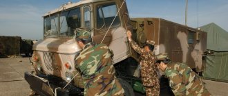
- removes the decorative element of the grille “glasses” covering the space around the headlights - unscrew the screws securing the headlights - disconnect the wire chips - take out the lamps - wrap the headlight in rags and carefully knock out the old glass with a hammer - use gloves or pliers to remove glass fragments stuck to the silicone,
be careful
— we use a knife to clean off the remnants of the factory silicone, degrease the surface — we make a technological hole almost close to the future new glass with a 2 or 3 drill — we try on the LED rings in place — we thread the wires from the rings into the hole made — we apply silicone in a thick stripe to the intended place inside the reflector (3 -4 mm) in a circle - we apply the rings of LEDs on top, without pressing too hard - to be sure, we draw a thin strip of silicone on top of the rings along their outer edge, so that the strip touches both the reflector and the ring -
do not poke your fingers there
and do not smear anything!
It fits as it should, the main thing is to place the rings exactly inside the reflector. — these two rings, when dry and provided they are in contact with the surface of the reflector, ultimately form the mount of Angel Eyes, the AG turns out to be, as it were, clamped inside them and, due to their low weight, are attached in this way reliably and effectively — let them dry for about 20-30 minutes so that the silicone “ got up". — let’s start gluing the glass and general sealing of the headlight: — draw a thin strip along the seat of the reflector — glue in the glass of the diffuser — to be sure, apply a thin strip on top of the glass at the point of contact with the reflector, here we actively use a finger
and a rag — coat all technological holes on the outside of the reflector , including the llama seat and our hole, which we drilled ourselves, pay special attention to the light bulb seat, there are many gaps there - we move on to laying the wires, draw plus and minus through the headlight housing and connect them to the Angel Eyes wires - install the headlight in place, also with second - we find a place in the engine compartment for a 4-pin relay, screw it on, connect the wires, I can’t tell you here, I’m not an electrician. I just already had a relay with wires and a free button. - we drill a hole for the button, I installed it between the emergency lights and the adjustment of the instrument lighting, we connect the wires, having previously inserted them either into the existing holes in the motor shield, or we drill ourselves - we check the operation of the relay and AG - you can connect the whole thing to the size wire, it's easier - that's it
DRL Philips on VAZ-2106
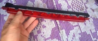
From the rest of the range, I liked the Philips DRLs. They are very compact, thin, contain 4/5/8 LEDs in the headlight and practically do not change the appearance of the car. As a result, the choice was made on them, namely on a design of 5 one-watt LEDs:
Such a pleasure costs 5000-6500 rubles, depending on the greed of the store, it’s cheaper when ordering online (definitely less than 5000 rubles), but I was taken for a ride in one such place, and I decided not to be greedy, I bought it in a store near my house for 5650 “wooden” .
The DRL kit includes two flat headlights, a control unit for them, mounting brackets and various small things such as plastic clamps, screws and neatly cut pieces of double-sided tape.
To install the DRL, we used a cordless drill, 2, 2.5 and 3.5 drills, a Phillips screwdriver, two self-tapping screws and a piece of wire about half a meter long. As for mounting points, it seems to me optimal to install the DRLs under the bumper, horizontally approximately at the level of the low beam headlights. At the same time, the DRLs themselves will not spoil the appearance of the car; when turned off they will be barely noticeable, and when turned on they will not be blocked by fangs. This installation scheme fully complies with the rules.
The basic sequence for installing headlights is as follows:
3. We try on the headlights, inserting them into the brackets (not yet completely). We finally install the brackets and tighten the screws.
4. Pass the wire from the headlight through the square hole in the back of the bracket. It should be noted that different headlights have different wire lengths. I installed the control unit next to the battery, according to this, you should select the headlights for left/right installation. They are no longer different from each other. Don't lock the headlights yet.
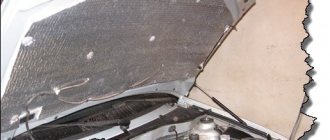
5. Open the hood and slightly pull out the rubber seal that covers the hole in the mudguards through which the wires to the sidelights pass. We insert a long wire into this hole from above so that it comes out from below under the wing, and its end remains in the engine compartment. If there are fender liners, they will need to be slightly bent at the front.
6. Insert the wire from the headlight into the hole in the fender. The connector takes some effort, but passes through it without loss. We pass enough wire through so that it also comes out from below.
7. We fasten the headlight connector to the piece of wire that was passed from under the hood, and pull the wire from the headlight into the engine compartment. We do the same with the second headlight. Don’t forget to put the seals back in place, placing the wires from the headlights in them.
8. Select a place to install the control unit. My attention was drawn to two holes in the mudguard next to the battery. I used one of them to install the block, and I had to make another one myself. For some unknown reason, the kit does not include screws for installing the control unit (apparently, it is supposed to be installed only with double-sided tape), so ordinary self-tapping screws (and the same tape) were used:
9. It is better to connect the control unit with the battery disconnected. We connect the black wire to the car body.
10. Cut off the tip of the red wire and remove a little insulation. We find the low beam headlight relay (the high beam has a higher current, so it is not advisable to perform the manipulations with the terminal described below), we find a thick pink wire on which there is always voltage, regardless of the position of the ignition key. We disconnect this wire from the relay, pass the red wire from the control unit through the casing to the terminal and pass it inside through the transverse slot in the terminal so that it is pressed to the terminal by the relay contact:
④AOTOGO 12V LED COB Car Daytime Light
Rating: 4.6 Price: from 28.90 rub.
up to
38.09 rub.
Go to store LED DRL strip is the most budget-friendly option available on AliExpress to create additional lighting for your car. The manufacturer assures that this product is universal and can be suitable for any car model. The buyer can choose from the following colors: white, blue or light blue. Color temperature varies from 6000 to 8000 K. The product is fully protected from water and dust and is easily installed under the hood on the surface of the headlight housing. When purchasing, you must select the number of pieces required for installation.
Advantages:
- price;
- simplicity.
Flaws:
- quality;
- durability.
Buy on AliExpress.com
All connection diagrams for daytime running lights
On the territory of the Russian Federation, amendments to the rules of the road (TRAF) have been in force for more than 8 years, according to which a moving vehicle during daylight hours must be indicated by low beam headlights, fog lights (FTL) or daytime running lights (DRL). Using headlights and fog lights for these purposes has a number of disadvantages. Therefore, drivers prefer to buy ready-made running light modules and install them in their cars themselves. How to properly connect daytime running lights so that their operation is safe and does not contradict current laws?
The main mistakes when making DRLs with your own hands
First of all, you need to figure out what kind of device it is. Daytime running lights are not dimensions! They need to be tested not at night, but during the day.
The lights must be visible from a great distance. Contrary to popular belief, when assembling DRLs from an LED strip with your own hands, you need to use the most powerful strip available. With such dimensions as the average running lights, it is quite difficult to exceed the permissible brightness using an LED strip.
Don't forget about cooling, but don't install too large radiators. Do not forget that the flow of incoming air when the car is moving practically replaces active cooling. Therefore, the radiator area can be half as large as under normal conditions for passive cooling of luminaires.
The nuances of turning on running lights
The basic requirements regarding installation, technical parameters and connection of navigation lights are listed in paragraph 6.19 of GOST R 41.48-2004. In particular, the electrical functional circuit of the DRL must be assembled in such a way that the running lights turn on automatically when the ignition key is turned (the engine starts). In this case, they should automatically turn off if the headlights are turned on.
Clause 5.12 of this standard states that headlights (FGS) should be turned on only after the lights are turned on, with the exception of short-term warning signals. When connecting DRLs yourself, this feature must be taken into account.
Correct connection of DRLs is not limited to a well-thought-out functional diagram. It's time to think about the stabilization unit for LEDs. In the running lights themselves, resistors act as a current limiter; however, due to voltage drops, resistors cannot limit the current to the same level. That is why a voltage stabilizer in the running lights connection circuit is extremely necessary. Otherwise, the service life of LED DRL modules is significantly reduced due to constant changes in on-board voltage. Some car enthusiasts claim that it is possible to connect running lights without a stabilizer.
Connecting and installing an LED driver is a waste of time, because the DRLs on LEDs shine regularly for months without any stabilization...
However, this statement is easy to dispute. The fact is that with each voltage surge, more than 12 V appears on the LED module, the forward current through the LEDs exceeds the nominal value, which leads to overheating of the emitting crystal. The brightness of the LEDs decreases, such DRLs will no longer be able to fulfill their immediate task - to warn oncoming drivers from afar, and over time they will begin to flicker and fail.
Using LED DRLs without a voltage stabilizer means spending at least several hundred rubles every year on new modules and wasting time replacing them.
For ease of understanding, the circuits below are shown without using a stabilizer.
Correct selection of components
The biggest challenge is to ensure a minimum luminous intensity level of 400 cd. Thus, the common LED size 5730 has a half-emission angle of 120 degrees. With a luminous flux of 50 lm, the luminous intensity will be only 16 cd. Calculations show that when installing a focusing system (lens and (or) reflector), concentrating the light flux within an angle of 20 degrees, the light intensity will increase approximately 2 times (taking into account the use of light flux and losses.), but in this case this is of decisive importance does not have.
5730 light emitting diode.
should pay attention to LEDs with a power of 1 W, or better yet 3 W (taking into account the practice of overstating the declared characteristics by manufacturers). Thus, a three-watt white LED from Epistar produces a luminous flux of 300 lm and a luminous intensity of 95 candelas. Taking into account the action of the focusing system, from four such LEDs you can get the minimum required 400 cd. Another condition is the radiation area of at least 40 sq.cm. With a LED lens diameter of 20 mm, its area will be about 3 sq.cm, and to obtain the required area you will need at least 10 such LEDs. It is possible that the total luminous intensity will not exceed the established 800 cd; to obtain a real result, laboratory measurements must be carried out.
3 Watt LED.
Such light-emitting elements cannot be installed without a heat sink - they are not designed for such a mode. The final list of materials will be like this:
- required number and type of LEDs (determined by calculation and selection);
- heat sink plate;
- focusing system;
- frame;
- connecting wires.
Next, you can begin assembling the DRLs.
| Light-emitting diode | Power, W | Angle, degrees | Color | Luminous flux, lm | Lens diameter, mm (emitting area, sq.cm) |
| ARPL-Star-1W-BCB | 1 | 120-140 | White | 120 | 20 (3) |
| Emitter 1W | 1 | 120 | 100 | 20 (3) | |
| Emitter LUX 1W | 1 | 120 | 130 | 20 (3) | |
| ARPL-Star-3W-BCB | 3 | 120-140 | 250 | 20 (3) | |
| STAR 3WR 3.6V | 3 | 150 | 20 (3) | ||
| High Power 3W | 3 | 120 | 200 | 20 (3) |
Switching on through dimensions or low beam
The second version of the DRL connection diagram involves using the power circuit of the side light bulb. To do this, the positive wire from the running lights is directly connected to the “+” from the battery. In turn, the negative wire is connected to the “+” of the side light, which is currently electrically neutral. As a result, the following current flow path is formed: from the “+” of the battery through the LEDs to the size, and then through the light bulb to the body, which serves as the minus of the entire circuit. Due to the low current consumption (tens of mA), the LEDs begin to glow, and the lamp spiral remains extinguished.
If the driver turns on the side lights, then +12 V appears on the positive side of the side lights, the potentials on the DRL wires are equalized and the LEDs go out. The circuit goes into normal mode, that is, current flows through the side light bulbs.
This circuit solution has several disadvantages:
This connection method can be improved by connecting the positive wire of the LED module not to the “+” of the battery, but to the “+” of the ignition switch, thereby eliminating the first drawback.
Some motorists use schemes for turning on running lights through a low beam lamp. That is, when the low beam is turned on, the DRLs automatically go out, but in other cases they work. In addition to the above disadvantages, this method does not comply with GOST R 41.48-2004 and traffic rules.
When parking a car at night, side lights are used to indicate it; the use of DRLs is prohibited.
What GOST says
Once the choice of daytime running lights has been made, they will need to be installed. And again, GOST R 41.48–2004 comes into force, which regulates the procedure for installing DRLs on cars of any type.
The rules for installing DRLs are to maintain precisely adjusted distances on the car body, from the road and between the units themselves:
- DRLs must be placed no lower than 25 cm and no higher than 150 cm above the road surface;
- from the edge of the machine in width - no more than 40 cm;
- if the width of the car is less than 130 cm, then the distance between two DRL blocks is allowed at 40 cm;
- if the width of the machine is more than 130 cm, the distance between the blocks should be 60 cm.
Many car owners are interested in the question of whether it is allowed to install DRLs on a car that was not originally equipped with them with their own hands:
- if allowed, what rules to follow;
- if not allowed, then on what grounds.
Installation of DRLs is allowed only if you study the entire volume of regulatory documents and strictly follow each point of GOSTs:
“The installation of daytime running lights on vehicles in operation is not mandatory, and paragraph 3.13 of Appendix No. 7 to the technical regulations on the safety of wheeled vehicles (hereinafter referred to as the Regulations) does not prevent the installation of lighting devices in order to eliminate non-compliance of the design of such vehicles with the requirements of the Regulations . Moreover, such lights must comply with the requirements of UNECE Regulation No. 87, and the method of their installation must comply with UNECE Regulation No. 48 or clause 1.3.29 of Appendix No. 5 to the Regulations.”
First Deputy Head of the Road Safety Department of the Ministry of Internal Affairs of the Russian Federation V.V. Shvetsov
Connection via a 4-pin relay from a generator or oil sensor
The following two methods have a common basis and imply the operation of daytime running lights only after the engine is started. The circuit for switching on DRL from the generator is based on switching a four-contact relay and a reed switch.
The DRL relay contacts are connected as follows:
After checking the reliability of all contacts, proceed to setup. To do this, start the engine and, by moving the reed switch near the generator, achieve its activation and a stable glow of the DRL. Then the reed switch is hidden in a thermal tube and fixed in the found place using nylon ties.
At the moment of starting the engine, and then the generator, the contacts of the reed switch and relay close, supplying power to the LED running lights. In this case, the side lamps remain turned off, since the current through the relay coil is small to light them.
In the absence of a reed switch, you can power the DRL from the oil pressure sensor. In this case, pin 86 is connected to the oil pressure lamp. The rest of the circuitry is duplicated.
Both schemes have a common drawback. They cannot be used if LEDs are installed in the dimensions.
Connection via 5-pin relay
Now it's time to learn how to connect running lights via a five-pin relay. The scheme is the most universal, and was assembled to eliminate the disadvantages of previous options.
First, about connecting the relay for DRLs:
The circuit with a five-contact relay works as follows. When you turn the key, +12 V is supplied to the DRLs, thereby turning them on. If you turn on the side lights or headlights, the relay will open contact 87a and close inactive contact 87. As a result, the DRLs will go out and the side lights will turn on. The circuit fully complies with the requirements of GOST and traffic regulations and can work with side lights even based on LEDs.
However, the circuit still has one negative point - the DRLs will turn on immediately after turning the ignition switch. That is, if you turn the key in the ignition but do not start the car, the DRLs will light up.
Despite the existing drawback, the circuit is quite successful, but in order to correctly connect the DRL via a five-pin relay, you will need to supplement the circuit with a voltage stabilizer.
This switching option is interesting because the path of current flow through the running lights is independent. This allows you to install light sources of any type and power in headlights and DRLs.
It couldn't be simpler
This is the simplest scheme, which involves connecting to a battery or generator as a power source.
The scheme provides that the DRLs will be activated simultaneously with the engine starting. The point is to connect the plus to the positive terminal from the ignition switch of your Renault Logan or the same Lada Largus, and fix the minus on the car body in any convenient place. Everything looks simple and extremely logical. But you should not rush to conclusions, nor should you make such a connection. After all, it has an obvious drawback.
If the system is assembled according to this scheme, the diodes from the DRLs will start working constantly while the key is in the ignition switch. There is no question of any coordination with other headlights here. Therefore, such a connection contradicts GOST and traffic regulations.