Characteristic
The adjustable operating parameters of the gas distribution mechanism include:
- moment of opening (closing) of valves;
- duration of valve opening;
- valve lift height.
Together, these parameters make up the valve timing - the duration of the intake and exhaust strokes, expressed by the angle of rotation of the crankshaft relative to the “dead” points. The valve timing is determined by the shape of the camshaft cam acting on the valve.
Different engine operating modes require different valve timing values. Thus, at low engine speeds, the valve timing should have a minimum duration (“narrow” phases). At high speeds, on the contrary, the valve timing should be as wide as possible and at the same time ensure overlap of the intake and exhaust strokes (natural exhaust gas recirculation).
The camshaft cam has a specific shape and cannot simultaneously provide narrow and wide valve timing. In practice, cam shape is a compromise between high torque at low rpm and high power at high crankshaft speed. This contradiction is precisely resolved by the variable valve timing system.
Depending on the adjustable operating parameters of the gas distribution mechanism, the following methods of variable valve timing are distinguished:
camshaft rotation;
the use of cams with different profiles;
changing valve lift height.
The most common are variable valve timing systems that use a camshaft rotation:
- VANOS (Double VANOS) from BMW;
- VVT-i (Dual VVT-i), Variable Valve Timing with intelligence from Toyota;
- VVT, Variable Valve Timing from Volkswagen;
- VTC, Variable Timing Control from Honda;
- CVVT, Continuous Variable Valve Timing from Hyundai, Kia, Volvo, General Motors;
- VCP, Variable Cam Phases from Renault.
Operating principle of VVT
The essence of the VVT system is to adjust the valve opening phases in real time, focusing on the engine operating mode. Depending on the design features of each system, this is implemented in several ways:
- turning the camshaft relative to the camshaft gear;
- activation of cams at certain speeds, the shape of which is suitable for power modes;
- changing the valve lift height.
The most widespread are systems in which phase adjustment is carried out by changing the angular position of the camshaft relative to the gear. Despite the fact that the operation of different systems is based on a similar principle, many automakers use individual designations.
- Renault - Variable Cam Phases (VCP).
- BMW – VANOS. Like most automakers, initially only the intake camshaft was equipped with such a system. A system in which hydraulic couplings for variable valve timing are installed on the exhaust camshaft is called Double VANOS.
- Toyota - Variable Valve Timing with intelligence (VVT-i). As is the case with BMW, the presence of a system on the intake and exhaust camshafts is called Dual VVT.
- Honda - Variable Timing Control (VTC).
- Volkswagen in this case acted more conservatively and chose the international name - Variable Valve Timing (VVT).
- Hyundai, Kia, Volvo, GM - Continuous Variable Valve Timing (CVVT).
How phases affect engine operation
The behavior of gases inside the internal combustion engine changes depending on the operating mode of the engine. For example, at idle speed the pistons move much lower than in operating mode at maximum speed. Accordingly, fluctuations in the gas environment in the intake and exhaust manifolds significantly depend on the operating point of the engine. The mentioned vibrations can be both beneficial, creating resonant boost (more details about acoustic boost in the article on the system for changing the geometry of the intake manifold), and harmful - parasitic vibrations, stagnation. That is why the speed and efficiency of filling the cylinders at different operating points of the engine differ significantly.
At low speeds, maximum cylinder filling will ensure late opening of the exhaust valve and early closing of the intake valve. In this case, valve overlap (the position in which the exhaust and intake valves are open at the same time) is minimal, so that the remaining exhaust gases in the cylinder are not forced back into the intake. It is precisely because of the wide-phase (“overhead”) camshafts on forced engines that it is often necessary to set higher idle speeds.
At high speeds, to get maximum performance from the engine, the phases must be as wide as possible, since the pistons will pump much more air per unit time. In this case, valve overlap will have a positive effect on the purging of the cylinders (the release of remaining exhaust gases) and subsequent filling.
That is why installing a system that allows you to adjust the valve timing, and in some systems, the valve lift height, to the engine operating mode, makes the engine more flexible, more powerful, more economical and at the same time friendlier to the environment.
Principle of operation
The operating principle of these systems is based on the rotation of the camshaft in the direction of rotation, which achieves early opening of the valves compared to the initial position.
The design of a variable valve timing system of this type includes a hydraulically controlled clutch and a control system for this clutch.
A hydraulically controlled clutch (commonly called a phase shifter) directly rotates the camshaft. The clutch consists of a rotor connected to the camshaft and a housing, which is the camshaft drive pulley. Between the rotor and the housing there are cavities to which engine oil is supplied through channels. Filling one or another cavity with oil ensures rotation of the rotor relative to the housing and, accordingly, rotation of the camshaft at a certain angle.
In most cases, a hydraulically controlled clutch is installed on the intake camshaft. To expand the control parameters in certain designs, couplings are installed on the intake and exhaust camshafts.
The control system provides automatic regulation of the hydraulic clutch. Structurally, it includes input sensors, an electronic control unit and actuators. The control system uses Hall sensors that evaluate the positions of the camshafts, as well as other sensors of the engine control system: crankshaft speed, coolant temperature, air flow meter. The engine control unit receives signals from sensors and generates control actions on the actuator - the electro-hydraulic distributor. The distributor is an electromagnetic valve and provides oil supply to and from the hydraulically controlled clutch, depending on the operating modes of the engine.
The variable valve timing system typically operates in the following modes:
- idle speed (minimum crankshaft speed);
- maximum power;
- maximum torque.
Another type of variable valve timing system is based on the use of cams of various shapes, which achieves a stepwise change in the opening duration and valve lift height. Well-known such systems are:
- VTEC, Variable Valve Timing and Lift Electronic Control from Honda;
- VVTL-i, Variable Valve Timing and Lift with intelligence from Toyota;
- MIVEC, Mitsubishi Innovative Valve timing Electronic Control from Mitsubishi;
- Valvelift System from Audi.
These systems have basically the same design and operating principle, with the exception of the Valvelift System. For example, one of the most famous VTEC systems includes a set of cams of various profiles and a control system.
The camshaft has two small and one large cams. The small cams are connected through corresponding rocker arms to a pair of intake valves. The large cam moves the free rocker arm.
The control system ensures switching from one operating mode to another by activating a locking mechanism. The locking mechanism is hydraulically driven. At low engine speeds (low load), the intake valves are operated by small cams, while the valve timing is characterized by a short duration. When the engine speed reaches a certain value, the control system activates the locking mechanism. The rocker arms of the small and large cams are connected using a locking pin into one unit, while the force on the intake valves is transmitted from the large cam.
Another modification of the VTEC system has three control modes, determined by the operation of one small cam (opening one intake valve, low engine speed), two small cams (opening two intake valves, medium speed), and a large cam (high speed).
How they wag on the engine
For some engines, the system is designed in such a way that the valve timing is a static value, and as a result we get an internal combustion engine with a rather low efficiency. Roughly speaking, the engine operates in different modes at different loads, and unchangeable phases lead to inefficient operation.
However, there are also internal combustion engines in which a phase adjustment system has been introduced. A bright representative of them is an engine with the VVTL-i system. In engines with such a system, when a certain engine speed is reached, the load is transferred to the valves by an additional pusher. This significantly increases efficiency.
What types of systems are there?
Honda's modern variable valve timing system is the I-VTEC system, which combines VTEC and VTC systems. This combination significantly expands the engine control parameters.
The most advanced type of variable valve timing system from a design point of view is based on adjusting the valve lift height. This system allows you to eliminate the throttle valve in most engine operating modes. BMW is a pioneer in this area with its Valvetronic system. A similar principle is used in other systems:
- Valvematic from Toyota;
- VEL, Variable Valve Event and Lift System from Nissan;
- MultiAir from Fiat;
- VTI, Variable Valve and Timing Injection from Peugeot.
In the Valvetronic system, changing the valve lift height is provided by a complex kinematic scheme, in which the traditional cam-rocker-valve connection is supplemented by an eccentric shaft and an intermediate lever. The eccentric shaft receives rotation from an electric motor through a worm gear. Rotation of the eccentric shaft changes the position of the intermediate lever, which, in turn, sets a certain movement of the rocker arm and the corresponding movement of the valve. The valve lift height changes continuously depending on the engine operating modes.
The Valvetronic system is installed only on the intake valves.
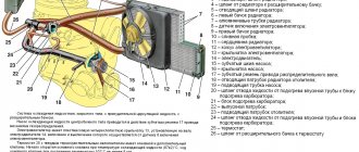
Gas distribution mechanism (GRM): device, purpose and principle of operation
The basis of any power units and the main component of internal combustion engines is a complex gas distribution mechanism (GDM). The purpose of the gas distribution mechanism is to control the intake and exhaust valves of the engine. On the intake stroke, it opens the intake valve, a mixture consisting of air and fuel or air (for diesel engines) enters the combustion chamber. During the exhaust stroke, the timing belt removes exhaust gases from the combustion chamber by opening the exhaust valve.
Gas distribution mechanism
The gas distribution mechanism consists of the following elements:
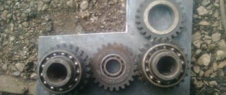
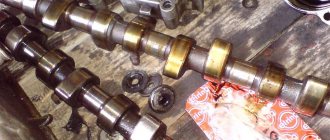
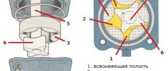
- The camshaft - made of cast iron or steel - whose task is to open/close the valves of the gas distribution mechanism when the cylinders operate. It is mounted in the crankcase, which is covered by the timing cover, or in the cylinder head. When the shaft rotates on the cylindrical journals, an impact occurs on the valve. It is acted upon by cams located on the camshaft. Each valve is acted upon by its own cam.
- Pushers are also made of cast iron or steel. Their task is to transfer force from the cams to the valves.
- Inlet and outlet valves. Their task is to supply the fuel-air mixture to the combustion chamber and remove exhaust gases. The valve is a rod with a flat head. The main difference between intake and exhaust valves is the diameter of the head. The inlet is made of chrome-plated steel, and the outlet is made of heat-resistant steel. The valve stem is made in the form of a cylinder with a groove necessary to fix the spring. The valves only move towards the bushings. To prevent oil from entering the combustion chamber of the cylinder, a sealing cap is installed. It is made of oil-resistant rubber. An internal and external spring are attached to each valve; washers and plates are used for fastening.
- Barbells. They are necessary to transmit force from the pushers to the rocker arm.
- Gas distribution mechanism drive. It transmits the rotation of the crankshaft to the camshaft and thereby sets it in motion, and it moves at a speed 2 times less than the speed of the crankshaft. For 2 rotations of the crankshaft, the camshaft makes 1 rotation - this is called the work cycle, during which 1 opening of the valves occurs.
This is the timing structure and the general diagram of the gas distribution mechanism. Now you need to figure out what the operating principle of the gas distribution mechanism is.
Gas distribution mechanism design
The gas distribution mechanism (GRM) consists of:
- one or two cam camshafts, each of which has its own gear;
- crankshaft gears;
- chain or belt drive.
The number of teeth on the camshaft gear is always 2 times greater than on the crankshaft gear.
Thanks to this, for two revolutions of the crankshaft, only one revolution of the camshaft occurs. This allows the cylinder head (cylinder head) valves to open and close depending on the engine stroke. The valve timing depends on the location of the camshaft cams. Therefore, on single-shaft engines, only simultaneous adjustment of the intake and exhaust phases is possible. On twin-shaft engines, separate adjustment of the intake and exhaust phases is possible. This allows you to optimize engine operation for various modes.
When the camshaft cam reaches the valve, it begins to press on it until the valve is completely open. Then the cam moves further and the spring begins to squeeze the valve, trying to close it. As soon as the pressure from the camshaft disappears, the spring completely closes the valve. The angle of rotation of the camshaft during which the intake or exhaust valves of one cylinder are open is called the valve timing.
Operation of the gas distribution mechanism
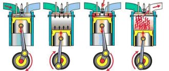
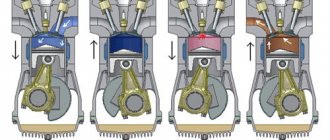
The operation of the gas distribution system is divided into four phases:
- Fuel injection into the cylinder combustion chamber.
- Compression.
- Working progress.
- Removing gases from the cylinder combustion chamber.
Let's take a closer look at the operating principle of the gas distribution mechanism.
- Fuel is supplied to the combustion chamber of the cylinder due to the movement of the crankshaft, which transmits its force to the piston and it begins to move from the so-called TDC (this is the point above which the piston does not rise) to BDC (this is the point, respectively, below which the piston does not fall) . With this movement of the piston, the intake valve simultaneously opens and the fuel-air mixture fills the combustion chamber of the cylinder. Having injected the required amount of fuel-air mixture, the valve closes. In this case, the crankshaft rotates 180 degrees from its initial position.
- Compression. Having reached BDC, the piston continues its movement. Changing its direction at TDC, at this moment the fuel-air mixture is compressed in the cylinder. When the piston approaches the highest point, the compression phase ends. The crankshaft continues its movement and rotates 360 degrees. And this concludes the compression phase.
- Working progress. The air-fuel mixture is ignited by the spark plugs when the piston is at the highest point of the cylinder. In this case, the maximum compression moment is achieved. Then the piston begins to move to the bottom point of the cylinder, since the gases formed during the combustion of the air-fuel mixture exert enormous pressure on the piston. This movement is the working move. When the piston lowers to BDC, the power stroke phase is considered completed.
- Removing gases from the cylinder combustion chamber. The piston moves to the highest point of the cylinder, all this happens under the force exerted by the crankshaft of the engine timing mechanism. At the same time, the exhaust valve opens and the piston begins to rid the combustion chamber of the cylinder of gases that were formed after the combustion of the fuel-air mixture in the combustion chamber of the cylinder. After reaching the highest point and releasing it from gases. The piston begins its downward movement. When the piston reaches BDC, the working phase of removing gases from the combustion chamber of the cylinder is considered completed, and the crankshaft rotates 720 degrees from its initial position.
For precise operation of the valves of the gas distribution system, synchronization occurs with the operation of the engine crankshaft.
The essence and role of valve timing
At the moment, there are engines in which the phases cannot be changed forcibly, and engines equipped with mechanisms for changing valve timing (for example, CVVT). For the first type of engine, the phases are selected experimentally during the design and calculation of the power unit.
Unregulated and variable valve timing
Visually, they are all displayed on special valve timing diagrams. Top and bottom dead centers (TDC and BDC, respectively) are the extreme positions of the piston moving in the cylinder, which correspond to the largest and smallest distance between an arbitrary point of the piston and the axis of rotation of the engine crankshaft. The starting points for valve opening and closing (phase length) are shown in degrees and are considered relative to the rotation of the crankshaft.
The phases are controlled using a gas distribution mechanism (GDM), which consists of the following elements:
- cam camshaft (one or two);
- valve mechanism;
- chain or belt drive from the crankshaft to the camshaft.
Gas distribution mechanism The
engine operating cycle always consists of strokes, each of which corresponds to a certain position of the valves at the inlet and outlet. Thus, the beginning and end of the phase depend on the angle of the crankshaft, which is connected to the camshaft, which controls the position of the valves.
For one revolution of the camshaft, the crankshaft makes two revolutions and its total angle of rotation during the operating cycle is 720°.
Circular diagram of valve timing
We will consider the operation of valve timing for a four-stroke engine using the following example (see picture):
- Inlet . At this stage, the piston moves from TDC to BDC, and the crankshaft rotates 180º. The exhaust valve is closed and the intake valve is subsequently opened. The latter occurs with an advance of 12º.
- Compression . The piston moves from BDC to TDC, and the crankshaft makes another rotation of 180º (360º from the initial position). The exhaust valve remains closed and the intake valve remains open until the crankshaft rotates 40º.
- Working progress . The piston moves from TDC to BDC under the influence of the ignition force of the air-fuel mixture. The intake valve is in the closed position, and the exhaust valve opens ahead of time when the crankshaft has not yet reached 42º BDC. At this stroke, the full rotation of the crankshaft is also 180º (540º from the initial position).
- Release . The piston moves from BDC to TDC and at the same time pushes out exhaust gases. At this moment, the intake valve is closed (it will open 12º before TDC), and the exhaust valve remains in the open position even after the crankshaft reaches TDC another 10º. The total amount of crankshaft rotation at this stroke is also 180º (720º from the starting point).
Timing timing also depends on the profile and position of the camshaft cams. So, if they are the same at the inlet and outlet, then the duration of opening of the valves will also be the same.
Timing faults
Main malfunctions of the gas distribution mechanism:
- Reducing compression and popping in pipelines. As a rule, it occurs after the appearance of carbon deposits, shells on the surface of the valve, and their burnout, which is caused by a loose fit of the intake and exhaust valves to the seats. Factors such as cylinder head deformation, breakage or wear of springs, jamming of the valve stem in the bushing, and a complete lack of space between the rocker arm and the valves also have an impact.
- Reduced power, engine tripping, and metallic knocks. These symptoms appear because the intake and exhaust valves do not open completely, and part of the air-fuel mixture does not enter the combustion chamber of the cylinder. The consequence of this is a large thermal gap or breakdown of the hydraulic compensator, which causes a malfunction and improper operation of the valves.
- Mechanical wear of parts, such as: crankshaft guide bushings, camshaft gears, as well as camshaft displacement. Mechanical wear of parts, as a rule, occurs when the engine has been operating for a sufficient period of time and the engine is operating within critical limits.
- Engine failure also occurs due to wear of the toothed belt, which has its own warranty period, the chain, which becomes less efficient after a long period of operation and constant exposure to it, the chain guide and the toothed belt tensioner.
In these cases, it is not uncommon to replace the gas distribution mechanism, but it is also possible to repair a damaged part of the gas distribution mechanism.
Timing belt diagnostics
The gas distribution mechanism has 2 inherent problems - loose connection of the valves to the sockets and the inability to fully open the valves.
A loose connection of the valves to the sockets is detected by the following indicators: popping noises that sometimes occur in the intake or exhaust pipes, a decrease in engine power. Factors that cause leaky valve closure may include:
- the appearance of carbon deposits on the surface of valves and seats;
- formation of cavities on working chamfers and curvature of the valve head;
- faulty valve springs.
Incomplete opening of the valves is accompanied by a knocking sound in the engine and a decrease in its power. This breakdown occurs as a result of a significant gap between the valve stem and the toe of the rocker arm. Typical timing failures include wear of camshaft gears, pushers, valve guides, camshaft displacement and wear of bushings and rocker arm axles.
Practice shows that the gas distribution mechanism accounts for approximately a quarter of all engine failures, and preventing these failures and restoring the timing takes 50% of the labor intensity of maintenance and repair work. To diagnose breakdowns, the following parameters are used:
- determine the phases of the gas distribution mechanism of the car;
- measure the thermal gap between the valve and the rocker arm;
- measure the gap between the valve and the seat.
Valve timing measurement
Such diagnostics of the engine timing belt is performed with the engine turned off using a special set of devices, including a pointer, a torque scope, a goniometer and other additional devices. In order to fix the period of opening of the intake valve on the 1st cylinder, it is necessary to rock the rocker arm around its axis, and then direct the engine crankshaft until a gap appears between the valve and the rocker arm. A goniometer for measuring the desired gap is placed directly on the crankshaft pulley.
Timing belt repair process
It is often necessary to carry out maintenance of the gas distribution mechanism. The main problem is wear of the journals, shaft cams and increased clearances in the bearings. In order to eliminate the gap in the crankshaft bearings, it is repaired by grinding the bearing journals and deepening the oil supply grooves. The necks need to be ground to repair size. After completing the repair work to restore the crankshaft, you need to check the height of the cams.
There should be no even the slightest damage on the supporting surfaces under the crankshaft journals, and the bearing housings must be free of cracks. After cleaning and washing the camshaft, be sure to check the gap between its journals and the hole in the cylinder head support.
To determine the exact clearance, you need to know the diameter of the camshaft journal, this will allow you to install the corresponding bearing. Having installed it on the housing, measure the inner diameter of the bearing, then subtract it from the diameter of the journal and thus find the size of the gap. It cannot exceed 0.2mm.
The chain must not have any mechanical damage and be stretched by more than 4mm. The timing chain can be adjusted: unscrew the locking bolt half a turn, turn the crankshaft 2 turns, then turn the locking bolt all the way.
Changing engine valve timing
The quality of operation of a car's internal combustion engine depends on many factors, such as power, efficiency, and cylinder volume.
The valve timing in an engine is of great importance, and the efficiency of the internal combustion engine, its throttle response, and stability at idle speed depend on how the valves overlap. In standard simple engines, timing timing is not changed, and such engines are not highly efficient. But recently, more and more often on cars of leading companies such as Honda, Mercedes, Toyota, Audi, power units with the ability to change the displacement of camshafts as the number of revolutions in the internal combustion engine changes.
What is engine valve timing
Briefly about the timing mechanism itself. The crankshaft is connected to the camshaft through a belt drive (in many modern internal combustion engines, a chain is installed instead of a rubberized belt) . When the driver starts the internal combustion engine, the starter turns the flywheel. Both shafts begin to rotate synchronously, but at different speeds (basically, during one revolution of the camshaft, the crankshaft makes two revolutions).
The camshaft has special droplet-shaped cams. When the structure rotates, the cam presses on the spring-loaded valve stem. The valve opens, allowing the air/fuel mixture to enter the cylinder or exhaust into the exhaust manifold.
The valve timing phase is precisely the moment when the valve begins to open the intake/exhaust port until the moment when it completely closes. Every engineer working on the development of a power unit calculates what the valve opening height should be, as well as how long it will remain open.
Valve timing diagram of a two-stroke engine
A two-stroke engine differs from a four-stroke engine in that its operating cycle takes place in one revolution of the crankshaft, while on a 4-stroke internal combustion engine it takes place in two revolutions. The valve timing in the internal combustion engine is determined by the duration of the opening of the valves - exhaust and intake; the valve overlap angle is indicated in degrees of c/v position.
In 4-stroke engines, the cycle of filling the working mixture occurs 10-20 degrees before the piston reaches top dead center, and ends after 45-65º, and in some internal combustion engines even later (up to one hundred degrees), after the piston has passed bottom point. The total intake duration in 4-stroke engines can last 240-300 degrees, which ensures good filling of the cylinders with the working mixture.
In 2-stroke engines, the duration of the intake of the air-fuel mixture lasts approximately 120-150º at the crankshaft turn, and purging also lasts less, so filling with the working mixture and cleaning exhaust gases in two-stroke internal combustion engines is always worse than in 4-stroke power units. The figure below shows the valve timing diagram of a two-stroke motorcycle engine, K-175 engine.
Two-stroke engines are used infrequently in cars, as they have lower efficiency, worse efficiency and poor purification of exhaust gases from harmful impurities. The last factor is especially relevant - due to tightening environmental standards, it is important that the engine exhaust contains a minimum amount of CO.
But still, 2-stroke internal combustion engines also have their advantages, especially diesel models:
- power units are more compact and lighter;
- they are cheaper;
- A two-stroke engine accelerates faster.
Camshaft timing sensor
Many cars in the 70s and 80s of the last century were mainly equipped with carburetor engines with a “trawler” ignition system, but many leading car companies even then began to equip engines with an electronic engine control system, in which all the main processes were controlled by a single block (ECU). Now almost all modern cars have an ECM - the electronic system is used not only in gasoline, but also in diesel internal combustion engines.
Modern electronics contain various sensors that monitor engine operation, sending signals to the unit about the state of the power unit. Based on all the data from the sensors, the ECU makes a decision - how much fuel needs to be supplied to the cylinders at certain loads (speeds), what ignition timing should be set.
The valve timing sensor has another name - the camshaft position sensor (CPS), it determines the position of the timing belt relative to the crankshaft. Its readings determine the proportion in which fuel will be supplied to the cylinders, depending on the number of revolutions and ignition timing. If the DPRV does not work, it means that the timing belt phases are not controlled, and the ECU does not “know” in what sequence it is necessary to supply fuel to the cylinders. As a result, fuel consumption increases, since gasoline (diesel) is supplied to all cylinders simultaneously, the engine operates inconsistently, and on some car models the internal combustion engine does not start at all.
Valve timing regulator
In the early 90s of the 20th century, the first engines with automatic timing change began to be produced, but here it was no longer the sensor that controlled the position of the crankshaft, but the phases themselves shifted directly. The operating principle of such a system is as follows:
- the camshaft is connected to a hydraulic coupling;
- the camshaft is also connected to this clutch;
- at idle and low speeds, the cam gear with the camshaft is fixed in the standard position, as it was installed according to the marks;
- when the speed increases under the influence of hydraulics, the clutch turns the camshaft relative to the sprocket (camshaft), and the timing phases shift - the camshaft cams open the valves earlier.
Three-stage variable valve timing
This system allows you to switch from small cams to large ones, depending on the operating mode of the internal combustion engine.
The transition between modes is achieved due to the fact that a special locking mechanism is activated. This locking mechanism is based on a hydraulic drive. When the engine operates at low speeds and under light load, the intake valves are actuated by small camshaft cams, and the valve timing in this mode has a short duration (narrow phase).
If the engine spins up to a certain speed, the control system activates the locking mechanism. As a result, the rocker arms of the small and large cams are connected, which ensures the rigidity of the structure. The connection is made using a special locking pin, and the force on the intake valves begins to come from a single large cam. The small camshaft lobes become inactive at high engine speeds.
Reaching maximum speed forces the intake valves to operate from a large central cam. This cam has a special profile, which is specially selected to achieve maximum valve lift, which means increased efficiency from the internal combustion engine at high power operating modes of the unit. This approach has significantly expanded the possibilities of controlling timing parameters for effectively regulating engine operation in various modes.
Variable valve timing system valve
The variable valve timing system (VPV) provides lower fuel consumption, reduces the level of CO in the exhaust gases, and allows for more efficient use of internal combustion engine power. Different global automakers have developed their own SIFG, which applies not only changes in the position of the camshafts, but also the level of valve lift in the cylinder head. For example, Nissan uses a CVTCS system that is controlled by a variable valve timing valve (solenoid valve). At idle, this valve is open and does not create pressure, so the camshafts are in their original state. The opening valve increases the pressure in the system, and the higher it is, the greater the angle the camshafts move.
It should be noted that SIFG are mainly used on engines with two camshafts, where 4 valves are installed in the cylinders - 2 intake and 2 exhaust.
Features of adjustable valve timing
At high speeds, the car engine requires more air volume. And since in unregulated timing valves the valves can close before a sufficient amount of it enters the combustion chamber, the operation of the engine turns out to be ineffective. To solve this problem, various methods of adjusting valve timing have been developed.
Valve timing control valve
The first motors with a similar function allowed step adjustment, which made it possible to change the phase length depending on the motor reaching certain values. Over time, stepless designs have emerged to allow for smoother, more optimal tuning.
The simplest solution is a phase shift system (CVVT), implemented by rotating the camshaft relative to the crankshaft at a certain angle. This allows you to change the timing of the opening and closing of the valves, but the actual duration of the phase remains unchanged.
To directly change the duration of a phase, a number of cars use multiple cam mechanisms, as well as oscillating cams. For precise operation of regulators, complexes of sensors, controllers and actuators are used. The control of such devices can be electrical or hydraulic.
One of the main reasons for the introduction of timing control systems is the tightening of environmental standards regarding the level of exhaust gas toxicity. This means that for most manufacturers, the issue of optimizing valve timing remains one of the most important.
Tools for setting valve timing
In order for the engine to operate without interruption, it is important to set the timing timing correctly and install the camshafts in the desired position relative to the crankshaft. On all engines, the shafts are aligned according to marks, and a lot depends on the accuracy of the installation. If the shafts are not aligned correctly, various problems arise:
- the engine is unstable at idle;
- The internal combustion engine does not develop power;
- There are shots in the muffler and popping noises in the intake manifold.
If the marks are wrong by a few teeth, it is possible that the valves may bend and the engine will not start.
On some models of power units, special devices have been developed for setting valve timing. In particular, for engines of the ZMZ-406/406/409 family there is a special template with which the camshaft position angles are measured. The template can be used to check the existing angles, and if they are incorrect, the shafts should be reinstalled. The device for 406 motors is a set consisting of three elements:
- two protractors (for the right and left shaft, they are different);
- protractor
When the crankshaft is set at TDC of the 1st cylinder, the camshaft cams should protrude above the upper plane of the cylinder head at an angle of 19-20º with an error of ± 2.4°, and the intake cam should be slightly higher than the exhaust camshaft cam.
There are also special devices for installing camshafts on BMW engines of the M56/ M54/ M52 models. The kit for installing the valve timing of the internal combustion engine of the BVM includes:
- torque wrench with extension;
- adjustment plate for double VANOS system;
- pins for fixing the flywheel;
- sleeve with spindle for tensioning the primary chain;
- a device for tensioning the secondary chain, as well as for blocking the tensioner plunger;
- camshaft retainer.
How to set valve timing
On most modern cars equipped with a mechanical timing belt, the valve timing is set the same. At TDC of the first cylinder. For this purpose, special marks are applied on the cylinder block and cylinder head housing, as well as on the camshaft and crankshaft gears. First of all, align the crankshaft marks. Then the marks of the camshaft(s) are aligned. After this, put on and tighten the chain or belt, then check the marks. If the marks are in place, turn the crankshaft 2 or 4 times and check the marks again. If the marks on the camshaft and crankshaft gears coincide with the marks on the cylinder block and cylinder head, then the phases are set correctly. If they differ, it is necessary to remove the chain or belt and repeat all operations.
Malfunctions of the variable valve timing system
The valve timing can be changed in various ways, and recently the most common is turning the r/shafts, although the method of changing the amount of valve lift and using camshafts with cams of a modified profile are often used. From time to time, various malfunctions arise in the gas distribution mechanism, due to which the engine begins to work intermittently, becomes “stupid”, and in some cases does not start at all. The causes of problems may be different:
- the solenoid valve is faulty;
- the phase change clutch is clogged with dirt;
- the timing chain has stretched;
- The chain tensioner is faulty.
Often when malfunctions occur in this system:
- Idle speed decreases, in some cases the internal combustion engine stalls;
- fuel consumption increases significantly;
- the engine does not develop speed, the car sometimes does not even accelerate to 100 km/h;
- the engine does not start well, you have to turn it with the starter several times;
- a chirping sound is heard coming from the SIFG coupling.
By all indications, the main cause of problems with the engine is the failure of the SIFG valve; usually, computer diagnostics reveal an error in this device. It should be noted that the Check Engine diagnostic lamp does not always light up, so it is difficult to understand that failures are occurring specifically in the electronics.
Often, timing problems arise due to clogging of the hydraulics - bad oil with abrasive particles clogs the channels in the coupling, and the mechanism jams in one of the positions. If the clutch “wedges” in its original position, the internal combustion engine runs quietly at idle, but does not develop speed at all. If the mechanism remains in the maximum valve overlap position, the engine may not start well.