Types of sensors
Modern sensors are based on a potentiometric design. It is quite simple, gives accurate measurements and is affordable. Such sensors are divided into lever and tubular. But they cannot be used in all types of cars.
Advanced non-contact sensors are able to determine the volume of fuel without diving into the tank. There are several types of such devices:
They are quite complex in design, so they can only be manufactured in a factory. But a simple do-it-yourself capacitive contact sensor can be done by an avid radio amateur who has the skill of working with a soldering iron and understands the principles of operation of a car’s fuel system.
The main principle of operation of such a sensor is that a signal is sent for a specific fuel level value. Of course, the float does not drop immediately as soon as the fuel level goes down, but after some time. In this regard, the device may give a slight error, which also depends on the design of the tank and fluctuations in gasoline or diesel. Data is displayed on the dashboard in digital or analogue form. The digital value is more accurate and has minimal error.
Types of contactless sensors
The most advanced modern developments are non-contact measuring instruments that determine the volume of fuel in the tank. The basic principle of operation is to determine the amount of fuel without immersing the sensor’s sensitive elements directly into the tank. There are several types of non-contact measuring instruments:
- Magnetic - its sensitive elements are tightly sealed and protected from contact with fuel. Information about the fuel level is still transmitted by a lever float connected to a magnet. Thus, the magnet moves through sectors, on each of which metal plates of different sizes are fixed. Information is transmitted from the magnet to the metal plate, creating an electrical impulse, this signal is read by the sensor, and we see the fuel level in the tank.
- Radio-controlled - data is transmitted to the dashboard via radio signal. The peculiarity of such devices is power supply. It is powered by a long-lasting battery. The shelf life of the power supply is up to 7 years. Accordingly, there are no wires, the battery does not consume energy, the indicators do not depend on electricity, and therefore are more accurate.
- Ultrasonic - installed on the outer surface of the tank and the control information unit. A specific program is installed for each type of fuel. This device has the highest explosion protection.
How to make a capacitive sensor
The operating principle of a capacitive sensor is to compare electrical capacitance data. In essence, the device is a regular capacitor. You can make such a device by having two metal tubes or plates on hand. The manufacturing rules are as follows:
1.Both electrodes are isolated from electrical contact.
If there is a lot of fuel in the tank, then the capacity of the sensor is higher, and it takes longer to charge. This measurement principle can be implemented using a built-in microcontroller. Part of the voltage is supplied to the input by a resistive motor. When the meter receives voltage, the microcontroller turns on. When the voltage reaches the peak level, the timer starts. From the timer, data is sent to the reflection module.
The sensor can be made from foil PCB by gluing the strips together. It is important that the gap between the plates is no more than 1.5 mm, and the length can be chosen at the discretion of the master.
Source
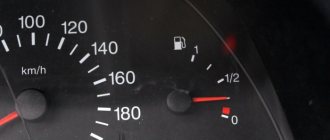
Digital fuel quantity indicator
I decided to make a digital indicator of the amount of fuel for a truck (bus), using a standard (rather mediocre) fuel level sensor.
Read the entire creation process and what came out of it in the article below.
Make a digital fuel level indicator using a standard level sensor.
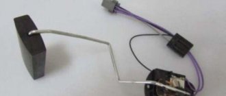
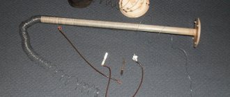
DUMP-39 , is . Let's dismantle it and examine it carefully.
As you would expect, there is a float, a rod, and a variable resistor. wait, more about the variable resistor. As they say, it is better to see once than to hear a hundred times:
The design is both logical and clumsy. It is logical that the slider slides not directly over the variable resistance (which is quite delicate), but along the metal taps from it, but for such an increase in reliability you have to pay for discreteness. The clumsy thing about this design is that, as can be seen in the photo, in the middle position of the float we have a fairly large “dead zone”, due to the very wide central outlet from the resistance. Why this was done, we can only guess, but what we have, we will have to work with.
So, we rummage through the Internet and look for information. Here's what I dug up:
In general, not a lot.
We take the tester and measure it, in the end we get the following picture: Connection diagram:
Measured sensor parameters:
In principle, this is enough to calibrate a digital indicator, if not for a couple of troubles:
1. The indicated fuel tank volume of 220 liters is not true; in fact, the tank holds more fuel.
2. In the extreme right position of the movable contact of the sensor, when there is supposedly no more fuel in the tank, in fact the float should already be below the tank level, which is, of course, nonsense (determined by the geometry of the tank and the fuel level sensor.
3. Having measured the geometry of the tank with a tape measure, we make sure that it is a rectangular parallelepiped with slightly rounded long edges, dimensions 40x112x60 cm . Multiplying the sides accordingly, we get an internal volume of 268 liters, which, you see, is very different from the declared 220 liters, and it is very doubtful that the internal partitions, mesh, fuel intake, etc. take up almost 50 liters .
4. As already written above, the resistance of the sensor over the length of its resistance is nonlinear.
Fill the tank full and control the voltage at the FLS output. It turns out that after reaching 1.57v, a good twenty liters of fuel still enter the tank.
We look at the graph of our fuel level sensor,
There is nothing pleasant in this picture; the sensor seems to be linear but has a significant kink.
With such a picture, we will either get accuracy in the middle, or at the ends of the broken line, or something in between by approximating:
Having received the formula with the correction and coefficient, you can, in principle, make something similar to a digital fuel level indicator; the coefficient
R 2 of the trend line of 0.97 is certainly not bad, you can, in principle, use anything greater than 0.95.
But you can get your own conversion factor for each straight line, which will be more accurate: We immediately measure the ADC value at the points we need so that the 5% tolerance on the divider resistors at the ADC input does not spoil anything for us and we get in the range from an empty tank (ADC822) to 1\ 2 tanks (ADC700) :
Causes of malfunction
The reasons why the fuel level sensor does not work or it shows incorrectly are the following faults:
- The float has lost its seal. This situation is relevant when a ball made of fragile plastic is used as a float, which can crack as a result of mechanical stress or as a result of operating the car in severe frosts. In this case, the float will be inside the liquid or, more often, it will simply sink and fall to the bottom. The result will be a constant reading from the device that there is no fuel in the tank. Repair measures include replacing the float or the entire assembly. Another rare option is that the float can simply detach from the lever on which it is attached and “go off on its own.”
- Deformation of the lever that holds the float. As a result, the float may lose mobility or reflect incorrect information. Often this situation occurs when the fuel module is inaccurately removed from the tank, but sometimes even as a result of long-term operation of the car on roads with uneven surfaces, that is, with constant vibrations while driving. You can try to return the lever to its original shape, but most often the corresponding lever is simply replaced with a new one.
- Damage to the sensor housing. As a result, the readings of the resistive elements may change or the lever that takes the corresponding readings may be damaged. In this case, the reason why the sensor does not show the fuel level correctly is the use of low-quality gasoline or mechanical shock loads on the part.
- Failure of resistive elements. This is a fairly common reason why the fuel level sensor does not work. Elements on the rheostat fail for natural reasons, that is, as a result of abrasion during long-term use. It is possible that the wear is partial, for example, in the middle. In this case, the instrument needle will twitch. It is also possible that there is no contact between the sliding element and the resistive track due to damage or wear of the resistive coating or loosening of the slider foot pressure. With such a malfunction, the arrow will lie at zero.
We recommend: Types of ignition systems
- Lack of electrical contact in a certain section of the circuit. As a rule, on contacts that are oxidized either by moisture or fuel. The wires, their insulation, or breakage may be damaged. There are also sometimes problems with electrical connectors.
- The signal wire has a short to ground. In this case, the value of its resistance will be distorted and tend to zero. With such a malfunction, the level sensor incorrectly displays the level, transmitting information that the tank is completely filled.
- The fuse responsible for the operation of the fuel level sensor has blown. The fuse number must be found in the electrical diagram of the specific vehicle.
- Failure to secure the sensor on the fuel tank body. For example, with a skew. As a rule, in such a situation, the smell of fuel spreads outwards, in particular, the smell of gasoline will be heard in the cabin.
- There are cases when the resistive board on which the slider moves simply falls off the fastening solder.
- Tubular fuel level sensors may have a broken signal wire. In this case, the arrow will constantly show an empty tank.
- Also, tubular sensors are characterized by a coating that can form on the guide post. This will naturally make it difficult (and even impossible) for the float to move. Plaque is usually formed as a result of using low-quality fuel (with a large amount of paraffin, gasoline instead of gasoline). In this case, the instrument needle will freeze in one position, and not necessarily in one of the extreme ones.
- For non-contact sensors, the magnetic sensor and/or its wiring may be damaged. Some of them have a special control and control board installed. The problem may be with her too. In this case, the sensor usually fails completely, that is, it does not indicate the fuel level at all.
Most often, problems arise with floats or resistive elements, which wear out over time and stop transmitting correct data. But note that when the fuel level is not displayed, it is not always the sensor that is to blame. Often the arrow does not work, and here the device on the panel, which, in fact, is a potentiometer, is to blame. Therefore, if the fuel sensor does not indicate the fuel correctly, then you need to remove it and check it with a multimeter and make a visual inspection.
Fuel level sensor (FLS). Assembly, circuits, production
Introduction
Looking ahead, I will say that there will be three articles, in this one I will talk about the simplest option for determining the level of diesel fuel (diesel only, use on gasoline vehicles is absolutely prohibited, as it is explosive). In the following articles, if the reader is of course interested, we will consider a digital fuel level sensor, and at the very end I plan to post the circuit diagram and firmware of the monitoring device that I described in this article.
A little theory
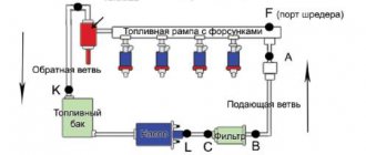
The most popular fuel level measurement sensors are an electric capacitor consisting of two tubes placed inside each other; a tank with fuel is installed, the level of which is measured. Diesel freely penetrates into the space between the tubes; a change in the fuel level in the tank is signaled by a change in the electrical capacitance of the sensor.
When the fuel level in the tank changes, the relative dielectric constant of the space between the capacitor plates changes, since the dielectric constant of fuel and air are generally different. And since the capacitance is directly proportional to the dielectric constant of the insulator, the electrical capacitance of the sensor also changes as a result. Sensors are mostly made of aluminum or copper because they are least susceptible to aggressive environments. Of the many ways to measure the capacitance value of a capacitor and then convert its capacitance into a proportional change in the DC voltage at the output, the pulse-width method was chosen as quite simple and reliable, but at the same time providing the necessary level of measurement accuracy. A disclaimer is immediately required, this is the simplest method in terms of finances and quite simple in terms of assembling the FLS method for determining the level of diesel fuel.
2. Description of the operation of the electrical circuit of the fuel level sensor
Fig 2. Schematic diagram of the fuel level sensor (FLS) (large diagram here)
To increase the stability and accuracy of the reading, all elements of the circuit are used with a minimum temperature coefficient.
Resistors are used with a 1% tolerance, microcircuits are selected with improved parameters in contrast to household analogues, for example: SE555N instead of NE555N, and LM358D instead of LM258D. A master oscillator is assembled on the U1 SE555N chip and elements R1, R2 and C1. Since the stability of the reading greatly depends on it, a precision polystyrene capacitor K71-7 1% is used as capacitor C1; they were usually installed in Soviet color TVs as master horizontal oscillators. It can be replaced with something modern, but the availability and price of these capacitors makes them very attractive, and they were born back in the distant year, when the USSR was very good at monitoring the quality of the elements produced. From the output of the 3rd microcircuit U1, rectangular pulses trigger a one-shot device assembled on the U2 SE555N microcircuit. As a single-vibrator capacitor, a sensor placed in the fuel is used, so its capacity will depend on the fuel level, and therefore, the pulse width at output 3 of the U2 microcircuit will also change on the fuel level. To ensure a linear dependence of the pulse width on the level of fuel filling of the sensor, the fuel sensor receives charging current from a current stabilizer made on the U3.2 chip and transistor Q1 BC856BT. Also, by changing the charging current, the circuit is adjusted to different sensor sizes. The circuit is configured by selecting resistors R6 and R7 to obtain 1.8-1.9 Volts at the output of the circuit, with a “dry” sensor. From output 3 of microcircuit U2, pulses are sent to an integrator assembled on elements R8 and C6. Next, the integrated voltage formed on capacitor C6 is supplied to the low-pass filter made on R10 and C10. Then the constant voltage is supplied to the direct current amplifier, made on the U3.1 chip. From the output of the 1st microcircuit U3.2, the signal, through a filter made on elements R17, C12, C14 and C15, goes to the output. Resistor R16 is used to prevent self-excitation of the amplifier when operating a capacitive load. The divider is made of resistors R9 and R11 and provides the necessary constant bias for the DC amplifier to operate in linear mode. The voltage stabilizer for powering the electronic circuit is placed according to the classical circuit on the U4 LM317MDT chip. As a result, at the output, we receive an analog signal empty tank 1.8V full 6.0V (there is a dependence on the height of the FLS), which is linear and directly proportional to the fuel level in the tank\tank\storage. Then, using the Kalman filter, you can remove fuel surges, calculate the average consumption, etc.
How do fuel meters work in different cars?
Modern cars, instead of the classic fuel meter, are equipped with a potentiometric design. The reason for this is several factors:
Although the potentiometer has a number of advantages, it also has a significant drawback - the contacts fail or oxidize due to their mobility; A potentiometric sensor for a car can be lever or tubular. Both types of meter are equipped with a plastic, metal or foam float.
Differences between lever and tube type sensors
The operating principle of both devices is identical, but there are still some differences. In a lever meter, the float located on the surface of the fuel is connected to the moving contacts of the potentiometer using a metal lever. Such a sensor includes a fuel pump, a potentiometer, a fuel intake, and transistors. When making a potentiometric meter with your own hands, remember that it is better to use a thick-film resistor - it will last much longer.
The lever device is universal and can be applied to any fuel tank.
The tubular measuring device moves the float using a special guide tube. Parallel to the tube there are resistance wires that will close the float ring. The main advantage of this operating principle is that the measuring device will be resistant to fuel fluctuations while the vehicle is moving (when turning, descending, ascending).
Such a sensor cannot be installed in every fuel system. The geometric parameters of fuel tanks will be limited. It is better not to install potentiometric meters on cars whose fuel contains alcohol - ethyl or methyl, as well as biodiesel. Such substances are harmful to contact surfaces. For vehicles using biodiesel or alcohol fuels, the best option is a non-contact fuel level sensor.
Types of contactless fuel level sensors
How do fuel level sensors work?
The basic principle of operation lies in the algorithm - for each value of the fuel level there is its own signal. However, this is only the superficial side of the issue. Modern measuring instruments are quite complex in their design. The fuel drops to a certain level and only after that the float drops after it. For some time, the indicator will show how full the tank is and will gradually go down to the desired level.
Therefore, measuring devices always provide some measurement error. The error rate depends on fuel fluctuations and tank geometry. Analogue or digital output signals can be installed on the instrument panel. Analog has practically lost its relevance due to strong measurement errors. Digital can correct and align data. Inaccuracies in readings are minimal and are possible at the stage of physical measurement.
Homemade fuel level sensor
Fuel level sensor - device (FLS)
In this article, our attention will be focused on cars where the FLS is used to indicate the fuel level, convert this level into volume and transmit the resulting value digitally or analoguely.
This device consists of a metal rod mounted into the fuel tank through a standard hole or a specially made hole of suitable diameter. The sensor is connected to the vehicle's monitoring system, where the required data is transmitted.
They are often high-precision universal devices, which allows them to be used not only in transport, but also in other equipment, and even in stationary facilities - factories, warehouses. This unit is closely interconnected with the fuel level indicator located on the instrument panel.
Today, there are a number of FLS variations - universal, ultrasonic, float, digital, electronic, but their common goal is the same - to correctly determine the fuel tank consumption, so that every driver has the opportunity to control their fuel costs. In addition, the device makes it possible to monitor the amount of drainage (the most useful option for taxi services, business managers and other organizations in which employees are able to drain government fuel) and fuel refills (in what volume, when and where they were carried out).
To be able to monitor the fuel level in more detail, it is necessary to install an appropriate device on the car with minimal error and increased sensitivity, which will provide the most accurate readings.
connecting the fuel level sensor
There are two methods for connecting the FLS to the vehicle’s on-board network, the design of which includes a ground switch:
- Connecting the FLS to the on-board network after the main switch. The sensor, in this case, will be de-energized immediately after the vehicle's mass is turned off. In this case, it will be impossible to find out the drain time when parked - the sensor will be turned off. This connection method is recommended for cheap sensors where there is no galvanic isolation.
- Connecting the sensor to the battery directly. This connection method is ideal from a practical and functional point of view. In addition, connecting the FLS directly to the battery is safe, since the sensor current consumption is only 10-48 mA. It is recommended to connect Pro Sensor sensors directly to the battery, since they are distinguished by the presence of a built-in galvanic isolation of up to 3000 V. In addition, the polymer body of this sensor is an insulator, as a result of which all electrical circuits are reliably protected from electrical breakdown. To connect other sensors directly to the battery, you will have to install additional galvanic isolation.
Manufacturing of capacitive fuel level sensor
The capacitance sensor for measuring fuel is based on the principle of comparing data on the electrical capacitance of the device. The design itself is simple - an ordinary capacitor. Therefore, a homemade fuel meter is a completely feasible device. It can be made from scrap materials - two metal plates or tubes. It is important to observe certain measures when manufacturing the sensor:
A homemade capacitive sensor consists of two modules connected by three wires. The first is a capacitive sensor module, the second is a display module. Two wires supply power to the sensor module; the third wire transmits a signal to the display module, which is transformed into an indicator of the fuel level.
Description of FLS
The FLS is designed to measure and control the fuel level in the fuel tank of a vehicle. Its function is to determine the fuel level, convert it into volume and transmit data for display on an analog or digital device. The regulator indicator is located on the dashboard, allowing the driver to monitor the amount of fuel in the gas tank.
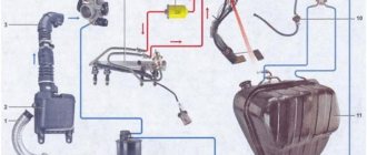
Device and principle of operation
Based on the purpose, you can deduce where the FLS is located. It is installed in the fuel tank. Depending on the type, it can be a separate element or combined with a fuel intake in the case of a carburetor engine. On a car with an injector, it is part of the fuel supply unit.
The most common are contact FLS. Their main element is a potentiometer. The operating principle is based on changing resistance. There are two types of such devices: lever and tubular. They differ in design.
The design of a lever-type device includes a float and a potentiometer connected by a lever. The potentiometer has two sectors, a slider that is in contact with the sectors. One end is connected to the lever, and the other to the float. The float is constantly on the surface. With fuel consumption, it lowers, and the slider moves with it, since they are connected by a lever.
In this case, the resistance of the fuel level sensor changes, the value of which provides information about the volume of the substance. The advantage of these devices is their simplicity of design, the disadvantage is the error of readings, especially for analogue indicators.
The tube type device does not have a potentiometer, but uses the principle by which it works.
The design includes a protective tube with a guide post along which the float moves. The float is connected to a resistance wire, which is connected to the indicator wires. Operating principle: fuel enters the tube through a hole, the float is on the surface and moves depending on the volume of fuel in the tank. The position of the float changes the resistance, which is transmitted to the indicators. A lever device gives more accurate readings, but is used less frequently due to design features: it may not be suitable due to the geometry of the gas tank.
Photo gallery
1. Design of a lever FLS
2. Design of a tubular FLS
The described FLS are not suitable for new types of fuel, as they quickly wear out in an aggressive environment. In this case, non-contact devices are used, such as a passive magnetic position sensor. In these devices, the sensitive element is sealed and does not come into contact with the fuel.
We recommend: Rules for operating a car air conditioner: what do you need to know?
The devices also use a float. It is connected to the permanent magnet by a lever. Moving along the sector on which metal plates of different sizes are fixed, it creates a magnetic field that generates a corresponding electrical signal.
Varieties
The design and operating principle of existing FLS have been described above. Thus, all fuel level meters can be divided into contact and non-contact. Representatives of the first type are lever and tubular devices. The lever type is a universal FLS, as it can be installed in any gas tank.
There are several types of contactless FLS:
- Ultrasonic fuel level sensor. It is located on the outside of the fuel tank and the control information unit. Depending on the type of fuel, a specific program is used. These meters are the most explosion-proof.
- For magnetic devices, the sensitive element is hermetically sealed and does not come into contact with the fuel. Information about the fuel level is also transmitted using a float, which is connected to a magnet. The created electrical impulse is read by the device and transmitted to the dashboard, indicating the fuel level in the tank.
- In radio-controlled devices, information is transmitted to the instrument panel using a radio signal. A distinctive feature of these devices is the power supply. They get tangled by the battery, which has a shelf life of about 7 years. They do not depend on the car's battery being charged, so they give more accurate readings.
Based on the transmitted signal, FLS are divided into analog and digital. The first type of instruments gives a large error in readings, so at present it is almost not used. Digital devices convert analog signals into digital data, and then analyze the data and correct errors taking into account the geometry of the fuel tank and uneven fuel levels. The electronic fuel level indicator provides the most reliable information; errors are possible only when physically measuring the volume of fuel.
You can make an FLS with your own hands. To do this, you need to be able to handle a soldering iron and have knowledge of electrical engineering. During manufacturing, it should be taken into account that the signal depends on the fuel level. The design of the device is quite complex. When the fuel drops to a certain level, the float also drops, but the data arrives at the dashboard indicator with some delay.
You can install either an analog or digital fuel level indicator with your own hands. The latter gives more accurate readings, as it can correct and align the received data.
A homemade fuel meter consists of two modules connected by three wires. One is a capacitive sensor module, the other is a display module. The sensor model receives power via two wires. The reflector module receives the signal via the third wire and converts it into an indicator of the fuel level (the author of the video is Vova Grishechko).
Capacitive fuel level sensor on ATMega8A
Knowing the fuel level in the tank is not only “cool”, but sometimes vital. In some cases, it is difficult to assess the fuel level in the tank due to its location or lack of transparency. For such cases, there are fuel level sensors. Today, float sensors are the most common. The operating principle of such sensors is quite simple. The float mechanism, depending on the fuel level in the tank, changes the position of the moving contact of the potentiometer. The voltage reading on the potentiometer is measured and converted into human-readable form. However, it is not always possible to install a float sensor due to its size. In addition, in devices where roll is a normal condition, for example, ultralight aircraft, the float mechanism may become skewed and jammed. In addition, the position of the tank in the ground and flight positions may differ, which may alter the operation of the float mechanism. However, there are other ways to measure fuel level. I'm talking about a capacitive fuel sensor . It is especially relevant if there is a need to get rid of moving parts.
Measuring principle and features
This method is based on measuring the electrical capacitance of the sensor, which, in turn, depends on the fuel level. The sensor used to measure the fuel level is called a capacitive fuel level sensor. The design of the sensor is quite simple and is nothing more than a capacitor. It consists of two plates, between which there is a gap that can be filled with fuel. The sensor can be made in the form of two metal plates or tubes inserted into one another. In this case, the surfaces of the two electrodes (capacitor plates) should not have electrical contact, and the gap between the plates should be freely filled with fuel when the sensor is immersed and just as freely released when the fuel level decreases. As fuel fills the space between the plates of the capacitor (sensor), its capacity changes. This method is only suitable for liquids that do not conduct electricity. This method will not allow you to measure the water level. Gasoline and other types of liquid fuels do not conduct electricity. By measuring the electrical capacitance of the sensor, you can estimate the fuel level in the tank. I would like to draw attention to some of the disadvantages of this measurement method. The fact is that the dielectric properties of the fuel can change when the chemical composition of the fuel changes. Those. When changing fuel type, you may have to calibrate the device. Despite this, this method allows you to install the sensor in the tank at an angle, or even mount it in the tank filler cap. The sensor has no moving parts, which is extremely necessary in some cases.
Is it safe to place an electrical circuit in a tank? Many people are concerned about this issue. What if there is a spark? Our sensor circuit is powered by a voltage of 5V, and the sensor is charged through a resistor of several megaohms. Under these conditions, spark formation is impossible. A voltage of 5V is negligible to cause a breakdown spark. In addition, an electric fuel level sensor already “floats” in the tank of any car. Low voltages and currents cannot cause a spark and ignition of the fuel.
I did not set myself the task of obtaining a super accurate sensor capable of measuring the fuel level to within 1mm and with an error of 0.1%, although this is quite possible. Considering that the sensor was created for devices where the fuel in the tank will be mobile, we are quite happy with a budget option with an error of 5%.
↑ Connection and initial setup
Connect the device according to the markings. [-]
Ground, to connect the ground it is advisable to choose a reliable contact.
[+]
Plus on-board power supply, 12 Volt, connects to any point on the on-board network after the ignition switch.
[G]
Dimensions, connects to the power supply circuit of the dimensions or dashboard lighting
[F]
Fuel sensor, to eliminate the influence of the original sensor, it is advisable to disconnect it and connect the device directly to the sensor line in the tank.
Turn on the ignition, connect a voltmeter in parallel to the power supply and check the voltage readings of the indicator; if necessary, adjust the indicator readings using trimming resistor R2