Oil channels
The engine lubrication system ensures that oil is supplied under pressure to all rubbing and rotating elements. The crankshaft main and connecting rod journals rotate in bearings. The bearings have an oil groove. To which oil is supplied from the oil channel. The pressure at which the oil is supplied. Creates an oil ring around the necks. The crankshaft journals rotate in the oil ring. Oil softens all impacts from emerging loads. This ensures that the crankshaft lasts a long time. Through the oil channels of the crankshaft from the main journals, oil is also supplied under pressure to the connecting rod journals. Provides rotation of the connecting rods. The connecting rod pin and cylinder liners are lubricated by splashing oil. For this purpose, there are calibrated holes in the connecting rod journals.
Oil is supplied to the crankshaft from the central channel. The channel has branches under each main journal of the crankshaft.
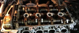
In parallel, oil is supplied from the central channel to the camshaft journals. The rotation of the camshaft occurs on the same principle as the rotation of the crankshaft. Oil creates a ring around each camshaft journal.
If the engine lubrication system design has a gas distribution mechanism design using valve rocker arms. There is a channel that supplies oil to the rocker shaft. Along the shaft to the rocker arm bushings. Oil flows through the bushings and channel in the rocker arms to the adjusting screw. The rocker arm pusher rods are lubricated through it. When using other timing belt designs. There are oil channels through which oil flows to them. Rockers, hydraulic compensators, pushers and other timing elements.
That is, all engine mechanisms are interconnected by oil channels. In which oil pressure is created.
Which engine parts are lubricated by gravity, splash and pressure.
On cars,
combined
lubrication systems
, when the most loaded engine parts (main and connecting rod bearings of the crankshaft, camshaft bearings, rocker arm bushings) are lubricated
under pressure
created by the oil pump, and the remaining parts are
lubricated by splashing or gravity flow
of oil.
Oil leaking through the gaps in the bearings of the crankshaft and camshafts is sprayed by the rotating parts and settles in the form of droplets and oil mist on the walls of the liners, camshaft cams, piston pins, pushers and other parts.
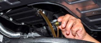
Oil is poured into the oil pan
through the oil filler neck located on the cylinder head cover.
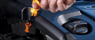
The crankcase ventilation air filter is installed in the neck cover. The oil level is measured
by the marks on the oil dipstick.
When the engine is running, oil is sucked in by the pump.
from the oil pan through an oil receiver with a strainer.
From the pump, oil is supplied through a channel in the cylinder block to the filter
.
From the filter, oil flows through the cavity in the second partition of the cylinder block into the main oil line
, and then through the channels in the partitions
to the main bearings and camshaft bearings
.
From the main bearings, oil is supplied through channels in the crankshaft cheeks to the connecting rod bearings
; through holes in the lower heads of the connecting rods, when they coincide with the holes in the connecting rod journals of the crankshaft, oil
is sprayed onto the walls of the cylinder liners
. Oil flows to the valve stems by gravity.
Malfunctions of lubrication systems that affect the durability of the engine, their elimination
Oil leakage
possibly due to a loose drain plug in the oil pan, damage to the sealing gaskets and external oil lines, or wear of the oil seals.
To eliminate the malfunction, it is necessary to restore the tightness of the connections, replace damaged and worn gaskets and seals.
Low pressure in the lubrication system
may be due to insufficient oil, the use of low-quality oil, wear of the crankshaft bearings or oil pump parts.
To eliminate the malfunction, you should check the oil level and, if necessary, top up; worn components and parts must be replaced. And the brand of oil must comply with the manufacturer's instructions.
Source
Oil pump
Oil pressure is created by the oil pump. Typically gear-type. Thanks to minimal gaps between liners, shaft journals, and calibrated holes. Designed for spraying oil. The system maintains the required operating oil pressure.
Any hydraulic system has the same operating principle. The oil pump will not begin to create pressure until the oil meets resistance. Or in our case, as long as there is resistance to oil in the liners and calibrated holes, the pump creates the required operating pressure.
High and low pressure line
The engine lubrication system has a low and high pressure line. High pressure is created by pumping oil into the system. The low line supplies oil to the pump. The elements of the low line are an oil intake and a tube supplying oil from the oil intake to the pump. The oil intake is an extension at the end of the supply tube. Covered with mesh. The mesh serves to prevent large elements from entering the pump. This could be carbon deposits, pieces of metal, shavings.
Causes of low engine oil pressure
The causes of low oil pressure in the engine can occur in various components. They are related to each other both with general engine wear and with the failure of individual engine mechanisms. Affecting the operation of the lubrication system as a whole.
Wear of parts.
Wear of the shaft journals and liners leads to an increase in the gap between them. It becomes easier for oil to come out from under the working surface. As a result, the load on the pump is reduced. It begins to create less pressure. Accordingly, the total pressure in the high-pressure lines of the engine decreases.
What oil pressure should be in the engine.
Oil pressure must create an optimally stable oil ring around the crankshaft and camshaft journals.
Consequences of low oil pressure
If the pressure is below normal, increased friction occurs between the shaft and the liner. The impacts that occur during operation of the shaft on the liner become stronger and more effective. And as a result, the earbuds break. The engine is jamming.
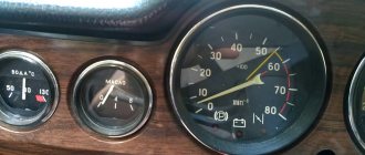
On average, on almost all engines the permissible low pressure is 0.2 Nm
Normal pressure at engine idle speed is from 1.5 to 2.5 Nm
At a driving speed of 60 km/h and a speed of 2000 rpm, normal pressure ranges from 3-4 Nm to 6.5 Nm
Higher pressure in the oil system is not created thanks to the pressure reducing valve. Modern cars are not equipped with oil pressure indicators. To monitor the pressure, an oil pressure indicator light is sufficient. It lights up if the pressure in the system drops below 0.2 Nm.
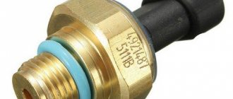
For example, the ZMZ 511 engine is installed on a Gas 53 car. It is very sensitive to wear. Low oil pressure is almost normal for these engines. Some drivers cover the warning light so that it does not shine in the eyes and does not distract. The engine started cold and the light went out for a short time before warming up. This is normal and nothing better could be desired. But no matter how low the pressure is, it ruins the engine. And you can’t count on him to work for a long time.
Oil pump wear
The oil pump, like any mechanism, is subject to wear. The gears and their contact planes are ground down. Oil begins to bypass inside the pump. The pressure in the system drops. Pumps very rarely fail. Most likely, the engine will become unsuitable for repair. Nothing is eternal. There are special stands for checking the operation of the pump. And if in doubt, the pump can be checked.
Oil intake mesh.
Mechanical damage to the engine sump.
A dent in the pan can cause a pressure drop. If the pan was dented inward from the impact, it could get very close to the oil intake. Partially block it. Just like when there is a blockage, the oil supply will not be enough to create normal pressure in the system.
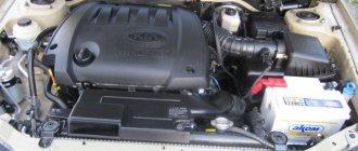
General device
The engine lubrication system includes:
- oil pan with oil intake
- oil pump
- oil radiator
- oil filter
- connecting highways and channels
Rice. Engine lubrication system diagram: 1 - oil pan; 2 — oil level and temperature sensor; 3 - oil pump; 4 - pressure reducing valve; 5 — oil radiator; 6 — oil filter; 7 - bypass valve; 8 - check valve; 9 — oil pressure sensor; 10 - crankshaft; 11 — nozzles; 12 — exhaust camshaft; 13 — intake camshaft; 14 - vacuum pump; 15 — turbocharger; 16 — oil drainage; 17 - mesh filter; 18 - throttle.
The purpose of the engine oil pan is to store oil. You can check the oil level in the pan using a dipstick, as well as an oil level and temperature sensor.
The oil pump is used to pump oil into the system. It is driven by a crankshaft, camshaft or auxiliary drive shaft. The most common are gear type oil pumps.
Rice. Single-section gear oil pump with built-in pressure reducing valve: 1 - inlet cavity; 2 - discharge cavity; 3 - pressure reducing valve
The oil is cleaned from carbon deposits and wear by an oil filter . Cleaning the engine oil is achieved by a filter element, which is recommended to be replaced simultaneously with an oil change.
Cooling and heating of engine oil is carried out by an oil cooler . The oil cooler circulates coolant, which heats the oil when the engine is cold and cools it when the engine is hot. The engine oil must have a temperature above 100°C in order for residual water to evaporate from it, but its temperature should not exceed the limit in the range from 138°C to 148°C.
The oil pressure in the system is monitored by sensors installed in the oil line. The sensor sends a signal to a lamp on the dashboard. Pressure information can also be sent to the engine management system. If the pressure drops above normal, the control system must stop the engine.
Modern engines may have oil level and temperature sensors. The information they receive is also displayed on the dashboard.
Constant operating pressure in the lubrication system is maintained using one or more pressure-reducing (bypass) valves, which are installed in the oil pump and filter.
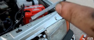
Oil pressure diagnostics.
The farthest point from the oil pump is the engine block head. Naturally on the rocker arms or on the camshaft if it is located in the cylinder head. The lowest pressure is formed. But for normal engine operation it must be present. Therefore, even if you just open the filler plug in the valve cover. The head parts are thoroughly lubricated. When the engine is running, oil splashes will be visible. If they are not there, it means the oil is coming in at low pressure. And even from this fact one can judge that there is a malfunction in the oil system. And you can already judge why the oil pressure light came on.
You need to find where the oil pressure sensor is located. Unscrew it. Install a mechanical pressure gauge in its place. It will accurately show the oil pressure in the oil system. Oil pressure is below 0.2 Nm at idle speed. Indicates that there is a malfunction.
Wear of the camshaft and hydraulic compensators.
If the design of the engine lubrication system involves placing a camshaft in the engine block. You can try inserting a dipstick between the camshaft journal and the bushing. If the dipstick works, then the wear is unacceptable for further work. If there are connecting rods, this will be difficult to do. But as an option.
The knocking sound of hydraulic compensators indicates a pressure leak in them.
Of course, a more accurate picture will be visible when the engine is completely disassembled. And all such measurements cannot give an accurate answer to the question of engine wear. The only reason why these measurements can be carried out is only to detect a cause not related to wear. Such as violation of seals, cracks. Perhaps the oil pump has failed or the pressure relief valve is stuck in one position. As a result, oil from the high pressure line is discharged into the return line.
Source
Operating principle
The car's oil system must be forced, under pressure, to ensure an uninterrupted supply of lubricant to the rotating elements of the engine. The pressure of the incoming mixture must be sufficient to ensure stable functioning of the working mechanisms in the friction units of the car.
Motor oil reduces the friction that occurs between two moving objects. The influence of friction can be reduced if a separating oil film is created between the moving planes, which will protect the rubbing parts from excessive mechanical loads. The size and strength of the protective layer is influenced by the shape of the contacting parts and the sanitary condition of their surfaces.
Subject to the operating conditions of the engine, the separating layer will have sufficient density to prevent direct contact of the surfaces. But under conditions of extreme loads, the strength and thickness of the film may decrease, and the parts will begin to touch. Such circumstances are called boundary lubrication.
Oil having a standard viscosity will help reduce the negative effect and prevent wear of the structure. In addition to viscosity parameters, the quality of the lubricant is affected by the pressure of the oil fluid and the temperature parameters of the engine.
Oil pressure indicators
The standard pressure force of lubricating fluids can only be achieved if there is a sufficient volume of oil emulsion in the sump of the unit. You can check the fluid level using a metal dipstick placed in the guide tube near the cylinder block.
Low lubricant pressure is observed at the time of first start-up and when the engine is idling, and high pressure is observed when the unit is operating at high speeds. Insufficient density of the lubricating fluid will not allow the formation of a separating film in the contact areas, which can lead to intense wear of parts.
Oil temperature
Low or high temperature conditions in any case negatively affect the protective qualities of the oil. Cold oil is too thick. This creates certain difficulties when moving the emulsion through lubrication channels. An overheated mixture, on the contrary, is too liquid to create a strong separating film on the rubbing surfaces. A thin layer of oil or lack thereof can lead to wear or engine failure.
The car owner can independently calculate favorable thermal conditions for stable operation of the power unit. To do this, you need to add +60°C to the ambient air temperature. As a result of this operation, we obtain the average temperature value, which should be recorded by the sensor on the dashboard inside the car.
Lubrication system design
A stable and uninterrupted supply of oil fluid to the rubbing surfaces is the main condition that affects the durability of the engine. Based on the principle of lubrication of friction units, the mixture supply system can be divided into several ways:
The forced method involves delivering oil fluid to the contact areas using an oil pump under pressure. Splash lubrication occurs through special nozzles that divide the oil flow into small droplets. Drops, in the form of oil mist, enter the friction units and lubricate the contacting surfaces.
Modern cars use a combined lubrication system, which combines the two previous methods. The crankshaft and camshaft bearings, pushrod struts and timing rocker arms are forcibly lubricated. The remaining engine parts are serviced by spraying or gravity flow.
Regardless of the method of supplying lubricants, engine lubrication systems must meet the following requirements:
Depending on the method of storing working fluid in the power unit, there are 2 types of lubrication systems:
The pan is designed for storing and cooling oil fluid. Inside the crankcase there is a metal, horizontally located partition called a damper. The damper serves to dampen oil vibrations while the vehicle is moving.
The use of wet and dry sump in a combined lubrication system
The combined system is most popular when creating cars in modern conditions. It involves supplying oil under pressure to all parts and mechanisms that most urgently need it, for example, bearings. Oil pressure is built up using an oil pump. All other parts are lubricated with oil emulsion.
In a combined system, different types of crankcase can be structurally used:
A wet sump means constantly filling it with oil. This principle is used on most standard cars. Its advantage is simplicity and reliability. However, there are also disadvantages. For example, if fuel gets into the lubricant, oil foam may form. Together with it, a large amount of air will enter the system, thereby sharply reducing the pressure and reducing the operation of the engine lubrication system to zero.
To avoid such troubles on some cars, a dry sump is used. The principle is that the oil is stored in a separate tank and supplied to the system from it. This eliminates the possibility of air intake when foam forms or the oil level drops.
The advantage of this system: ensuring stable engine operation when the car passes obstacles with a large angle of inclination, the size of the power plant is significantly reduced due to the small size of the crankcase, oil consumption and its quantity in the engine are reduced.
Engine lubrication system
Purpose of the lubrication system and its additional functions
The lubrication system (lubrication system) is designed to supply oil to rubbing surfaces in order to reduce friction forces, as well as to cool parts, remove carbon deposits and wear, and protect engine parts from corrosion. In addition, the oil significantly seals the gaps between mating parts. In addition to the listed functions, the lubrication system can also perform specific tasks. Engine oil from the lubrication system is used in hydraulic valve thermal clearance compensators, hydraulic tensioners for the gas distribution mechanism drive, in valve timing control systems, in the hydraulic drive of the cooling system fan, etc.
If the working surfaces of the parts mating in a movable joint are absolutely dry, then dry friction occurs, accompanied by intense heat release, wear of the surfaces, and requiring significant energy expenditure for the relative movement of the parts.
Friction between surfaces separated by a sufficiently thick layer of oil is called fluid friction. In this case, the force required for the relative movement of parts is significantly reduced and the wear of their working surfaces is significantly reduced.
In an internal combustion engine, persistent fluid friction can only be achieved in the crankshaft bearings at operating conditions.
The remaining conjugate pairs move back and forth or swing, so it is not possible to maintain an oil layer of sufficient thickness on their surfaces. Such friction, when the working surfaces are separated only by a thin film of oil (less than 0.1 mm thick), is called boundary friction. Depending on the film thickness, boundary friction can be semi-liquid or semi-dry. The latter is characterized by the possibility of “grabbing” microprotrusions of rubbing surfaces, a tendency to scuffing and erosive wear.
Semi-fluid friction is most typical for parts of the cylinder-piston group. In the “exhaust valve – guide bushing” pair, semi-dry friction may occur.
The supply of oil to the rubbing surfaces must be uninterrupted. With insufficient lubrication, engine power is lost, wear on parts increases and the likelihood of failure increases due to destruction of crankshaft bearings, jamming of pistons, distribution mechanism, etc.
Excessive lubrication should not be allowed, as this can lead to oil getting into the combustion chamber and onto the spark plug electrodes, resulting in increased carbon formation in the piston heads, combustion chamber walls and valves. This leads to overheating and interruptions in engine operation, as well as excessive oil consumption.
Requirements for the engine lubrication system
The requirements for the lubrication system are based on its functions and tasks:
5.1. Lubrication system devices
The oil pump
(Fig. 38) is designed to supply oil under pressure to the most loaded surfaces of parts and to devices for cleaning and cooling it. Gear-type pumps are used, usually driven by a camshaft. There are single-section and two-section pumps. The second section supplies oil to the radiator for cooling.
Rice. 38. Oil pump with oil receiver: a - design; 6 - operation diagram; c - diagram of oil flow with a clean grid; d - diagram of oil flow in case of grid clogging; 1 — housing of the lower section of the pump; 2 - bolt connecting the housings of the pump sections; 3 - gaskets; 4 — driven gear wheel of the upper section; 5 - pump shaft; 6 — body of the upper section; 7 — drive gear of the upper section; 8 — retaining ring; 9 — oil pump cover; 10 - pin; 11 — drive gear of the lower section; 12 — driven gear of the lower section; 13 and 15 - pressure reducing valves; 14 — installation location of the oil radiator valve; 16 — upper section; 17 — lower section; 18 — oil receiver body; 19 — tube; 20 - spring; 21 - mesh
The oil pump consists of a housing in which gears are located (the gap between the ends of the teeth of the gears and the walls of the housing is kept to a minimum); a drive shaft on which the drive gear is secured by means of a key; covers; pressure reducing valve; traffic jams. The driven gear rotates freely on the axis.
Oil is transported in the cavities between the teeth of the gears and is forced into the discharge passage as the teeth mesh.
The pressure reducing valve protects the oil supply system from excessive pressures that occur when starting a cold engine when the oil viscosity is high. The pressure reducing valve is located in the channel connecting the discharge and suction cavities. The channel is closed by a ball or piston pressed by a spring. Using a plug, the compression of the spring and, consequently, the pressure in the oil line are regulated. As the pressure increases, the piston moves away from the seat and oil passes from the discharge cavity to the suction cavity.
Oil receivers
serve to collect oil from the oil pan and, as a rule, are the primary filter for cleaning it. The filter mesh is held in the housing by a spring. There are ribs on the body into which the edge of the mesh rests, forming gaps between it and the body. When clogged, the filter mesh bends and oil enters the pump through the cracks. The attachment of the filter mesh may be different.
Oil filters
(Fig. 39) are used to clean the oil from mechanical impurities (wear products of rubbing parts, carbon deposits, etc.). Depending on the operating principle, oil filters are divided into slot and centrifugal filters. In slot filters, the size of the retained particles is determined by the size of the holes (slots) through which the oil passes. In centrifugal filters, particulate matter is removed from the oil by centrifugal forces. Depending on the size of the particles retained, filters are divided into coarse filters (particles up to 40 microns) and fine filters (particles up to 1-2 microns). Fine filters have high resistance and are connected in parallel. About 10% of the oil passes through them.
Rice. 39. Oil filters: a - full flow; b - centrifuge; 1 — drain plug; 2 - drain tube; 3 — filter housing; 4 — oil pressure indicator sensor; 5 — bypass valve spring; 6 - bypass valve; 7 - spring; 8 — drain pipe bolt; 9 — seal of the filter element; 10 - cover; 11 - oil line; 12 — filter element; 13 — emergency oil pressure reduction sensor; 14 — mating plane of the body; 15 — wing nut; 16 — casing; 17 - mesh filter; 18 — rotor axis; 19 — rotor cap; 20 and 21 - gaskets; 22 — rotor housing; 23 — centrifuge body; 24 - jet; 25 — thrust ball bearing; 26 — steel reflector; P - reaction force
Currently, full-flow fine filters with a large filter surface are widely used. Such filters are sometimes equipped with a coarse cleaning section. Fine filters connected in series to the main line must have a bypass valve.
The slot filter consists of a housing, a drain tube, a cardboard filter element, a spring and a cover, which is bolted to the housing.
The oil pumped by the pump is supplied to the filter through an oil line, seeps through the micropores of the cardboard filter element, passes through the holes inside the drain tube and enters the cylinder block through the channel.
Centrifugal oil filters (centrifuges) with a jet drive are usually fine filters. They are included in the lubrication system sequentially and consist of a housing, a fixed hollow axis on which a rotating rotor with a cap is located, and a filter cap. Oppositely directed jets are screwed into two bosses of the rotor bottom. Oil under pressure is supplied to the filter through the hollow axis, and the rotor cavity is filled. Then the oil enters the tubes and flows out at high speed through the jets into the body cavity and drains into the oil pan. The reactive tangentially directed force created by the oil flowing out of the nozzles causes the rotor together with the cap to rotate at a rotation speed of 6000-8000 min-1. When rotating together with the oil cap, heavy mechanical particles are thrown back by centrifugal forces to the inner wall of the rotor cap, forming a dense sediment on it, and from purified oil flows out of the jets. If the centrifuge is used as a full-flow fine filter, then part of the oil (10-20%) is used for the jet drive, and the rest enters the main oil line under pressure.
Modern centrifuges use not only a jet drive, but also the principle of a hydraulic turbine. In this case, the oil entering the centrifuge rotor is directed under pressure to the blades of the turbine installed in it and spins them. Therefore, the loss of oil to the jet drive is eliminated, and the entire amount of oil supplied by the pump and subjected to cleaning is supplied to the rubbing surfaces of the parts.
Oil radiator
. The required oil temperature (80-110 °C) is maintained using two systems - cooling and lubrication, the operation of which is closely interconnected.
Rice. 40. Oil cooler: 1 and 4 — hoses; 2 — oil radiator; 3 - tank; 5 - tap; 6 - fitting with safety (limiting) valve
Oil radiators (Fig. 40) are similar in design to tubular-plate radiators of the cooling system or are made of finned tubes. Oil is pumped through the radiator either by an independent oil pump (section), or taken from the main line fed by the main pump through a nozzle. The section of the pump supplying oil to the radiator is equipped with a bypass valve adjusted to excess pressure (0.12 MPa). If the radiator is powered by a common pump, then a safety valve is introduced into the lubrication system, which turns off the radiator when the pressure in the system drops to 0.1 MPa.
Source