LPG equipment installed on a car allows you to use cheap gas rather than expensive gasoline as fuel for the engine. It is for the sake of saving that many car owners install gas equipment on their cars. But how do you understand which equipment is better and how one generation of gas equipment differs from another?
This is both difficult and simple at the same time. It’s complicated because it’s new and unknown, but it’s simple because there’s nothing fantastically complicated about it.
By the way, on our website there is an excellent article about installing gas equipment on a car, which also discusses in detail the issue of the procedure for registering it with the traffic police.
In this material we will consider the following questions:
- The design and principle of operation of gas equipment on a car;
- Evolution of generations of automotive gas equipment: LPG 1/2/3/4/5/6th generations;
- How to choose gas equipment for a car and which gas equipment is better?
And at the bottom of the page, watch an informative video about the pros and cons of installing gas equipment in a car.
Which HBO to choose for a car?
To install HBO on a car, four generations of equipment are used.
The first generation devices were used at the stage of introducing natural gas as fuel. The first natural gas engines were equipped with such devices.
HBO for a first generation car
The second generation systems were implemented on cars with gasoline engines. Widely used on modern models with carburetor engines.
HBO second generation
The third generation equipment was placed during the transition from carburetor-type engines to equipment with injection ignition. The use of devices of this generation is an experimental area.
Third generation HBO
Fourth generation equipment is used on modern models with injection ignition. The design is equipped with an automatic control unit. Due to the complexity of the design, the units are installed in special technical centers.
Fourth generation HBO
Introduction
LPG
(liquefied petroleum gas) is a natural gas produced from two sources. It is a by-product of crude oil and gas produced by the cracking process.
LPG consists of two gases: propane and butane, which can be used separately or as a mixture. Since the composition of LPG is similar to the composition of evaporated gasoline, the equipment of a gasoline internal combustion engine will not require fundamental changes in the fuel system. For these purposes, gas cylinder equipment is used.
Attention!
Gas equipment operates under excess pressure, so safety regulations must be followed. The main safety requirement when operating a forklift on LPG is to regularly check the tightness of the equipment and immediately eliminate the causes of leaks. When leaking from a gas system, LPG evaporates by absorbing heat from the environment, so when it comes into contact with human skin, burns remain. LPG is heavier than air and should not be discharged in areas where there are pits of any kind. If a leak occurs not in the cylinder, but in some other element of gas equipment, immediately close the cylinder valve tightly and leave the engine running until the gas pipeline is completely empty. It is prohibited to operate a forklift with an expired cylinder inspection period.
Self-installation of gas equipment
Second-generation equipment has become most widespread. It is characterized by simplicity of design and installation. Distinctive advantages allow you to install LPG on a car yourself.
Connection diagram for gas equipment
System installation work is carried out in the following order:
- Installation of the cylinder.
- Installation of shut-off valves.
- Fastening of mixers and valves.
- Installation of dispenser and gearbox.
- Fixing the control panel.
- Checking the tightness and operation of the system.
Since the start of car production (1970), the Gorky Automobile Plant has introduced a large number of proposals to increase its reliability and durability, as well as comply with safety standards and reduce the labor intensity of maintenance.
To meet the needs of the national economy and exports, the plant produces several modifications of the basic GAZ-24 car.
The GAZ-24-01 taxi car differs from the GAZ-24 car in the installation of an engine with a reduced compression ratio (for operation on A-76 gasoline), the presence of a taximeter and a taxi identification lamp. The radio receiver and antenna are not installed.
The GAZ-24-02 station wagon (Fig. 2) is designed for transporting people and small cargo. The car body has three rows of seats. When the seats of the 2nd and 3rd rows are folded, a flat platform for cargo is formed, for improved access to which there is a door in the rear of the body. Due to the increased load, the car has reinforced tires and rear springs.
The GAZ-24-03 ambulance is designed for transporting patients and visiting doctors to provide emergency medical care. The room for transporting patients is separated from the driver's cabin by a partition and has an independent heater. The vehicle is equipped with a searchlight and a signal light with a red cross designation.
The GAZ-24-04 station wagon car is similar to the GAZ-24-02 car, but has equipment for working as a taxi car.
In addition to these modifications, in order to reduce air pollution in large cities, the Gorky Automobile Plant has prepared the production of a gas-cylinder taxi car GAZ-24-07.
General information about the GAZ-24 car
Description of modifications of GAZ cars Run-in of a GAZ-24 car Lubrication of a GAZ-24 car Frequency of maintenance of a GAZ-24 car Maintenance after 12-12.5 thousand kilometers Maintenance after 48-50 thousand kilometers Seasonal and maintenance as needed and additional maintenance Use with a jack when lifting the car Preservation of the car and preparation for storage
GAZ-24 engine design
Crank and gas distribution mechanisms Lubrication system Cooling system Power supply and exhaust system
Engine maintenance and repair
Maintenance, care of the lubrication system Care of the power system, care of the fuel pump Care of the carburetor Care of the timing belt Disassembly, repair and assembly of individual engine components and systems, water pump Fuel tank and fuel pump Carburetor K-126G Engine mounting Engine malfunctions and their elimination, checking the technical condition Engine repair Removing and installing the engine Engine disassembly procedure Assembling the engine Subassemble the connecting rod and piston group Subassemble the camshaft Dismantling and assembling the oil pump Disassembling and assembling the distributor drive
Transmission
Clutch device Maintenance of the clutch Repair of the clutch Dismantling the driven disk of the clutch Clutch assembly Installation of the clutch hydraulic drive Gearbox structure Gear shift mechanism Maintenance of the gearbox Repair of the gearbox, disassembly Assembling the gearbox Cardan transmission device Maintenance of the cardan transmission Repair of the cardan transmission Rear axle arrangement Rear axle maintenance bridge Repair of the rear axle Adjustment of the rear axle Assembling the rear axle
Chassis
Front suspension design Maintenance of the front suspension Checking and adjusting the angles of the front wheels Repair of the front suspension Replacing shock absorbers, threaded bushings of the front suspension Replacing rubber bushings Replacing the kingpin of the front suspension Replacing the bearings of the front wheel hubs Rear suspension arrangement Repair of the rear suspension Shock absorber design, maintenance of shock absorbers Repair of shock absorbers Wheel and tire installation, wheel and tire maintenance, repair
Control mechanisms
Steering device Maintenance of the steering, lubrication Adjustment of the steering mechanism Repair of the steering, disassembly Assembling and adjusting the steering
Brake system design
Brake system drive Automatic brake adjustment device Main brake cylinder Brake drive separator Brake warning light, parking brake system Maintenance of brake systems Adjustment of foot brakes, adjustment of hand brake Repair of brake systems, disassembly Assembly of the brake system
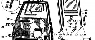
Car body
Body structure of the GAZ-24 car Glasses, doors of the Volga body Seats, seat belts, upholstery Ventilation and heating system Body structure of the GAZ-24-02 car Body maintenance Care of chrome parts Body repair Windshield installation
Electrical equipment
Battery design Battery maintenance Electrolyte density Battery charge Battery storage Generator design Generator maintenance Voltage regulator device Voltage regulator maintenance, voltage regulator repair Starter device Starter maintenance Starter disassembly Starter adjustment Ignition system design Ignition system maintenance, breaker Technical maintenance of spark plugs Repair of the ignition system Repair of the ignition switch Lighting and light signaling device Maintenance of lighting and light signaling Repair of the lighting and light signaling system Installation of sound signals, maintenance of sound signals Windshield wiper device, maintenance of a windshield wiper Installation of devices for washing and blowing window glass Control device devices Maintenance of control devices Antenna structure
Read about the structure and design of the GAZ 24 Volga car...
Category of articles on equipment repair
How to install a gas cylinder
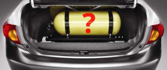
When installing gas equipment on your own, two types of cylinders are used:
HBO equipment
- cylindrical cylinders;
- toroidal cylinders.
Cylindrical cylinders have an oblong shape. To protect against gas leakage, they are equipped with a shut-off valve. Used in cars with a spacious trunk and on trucks.
Toroidal cylinders have a “tablet” shape. Used in cars with a small trunk.
The cylinder is mounted in the free space of the body. To protect against displacement, they are secured with steel strips. The ends of the strips are connected with bolts.
After mounting and securing the cylinder, the end of the filling valve is brought out. The end of the hose with a fitting is secured under the rear bumper or under the rear fender.
Gas pipeline wiring
Gas pipeline wiring - what it looks like
After installing the cylinder, a gas pipeline is installed from the tank to the engine compartment. For safety reasons, the pipeline is laid outside the car.
The diameter of the hole in the container is taken to be 1-2 mm larger than the diameter of the pipe. The difference in diameter is compensated by inserting a piece of plastic pipe. The resulting gap serves for additional ventilation of the multivalve. The edges of the hole are treated with anti-corrosion mastic.
The gas pipeline wiring is placed in the niche of the fuel line. The pipe is fixed in a constant position using steel clamps. After installing the pipe, begin installing the mixer and valve.
How to install a mixer and gasoline valve
The mixer is mounted between the carburetor and the manifold. The joints are sealed with rubber gaskets or silicone sealant. Careful sealing of joints protects cylinder equipment from air entering the system.
Gasoline valve for HBO
The gasoline electric valve is installed from the side where the fuel pipeline connects to the gasoline pump.
Attention! The gasoline electric valve is installed after the gasoline pump. Otherwise, the fuel pump will not be able to supply fuel to the carburetor.
To install the valve, the necessary part of the pipe is cut in the area between the fuel pump and the carburetor. A valve is inserted into the resulting incision. The joints are sealed and clamped with clamps.
Then proceed with the installation of the gas valve. It is installed on the opposite side of the gasoline electric valve. The outlet of the fuel line is connected to the gas valve.
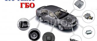
Gas engine power supply system and general diagram of the device
The power supply system for gas internal combustion engines, which is installed on cars, is a dosing system that allows the use of liquefied gas instead of gasoline. Its kit includes:
- a fuel cylinder, which can have different shapes;
- fuel type switch mounted in the car interior;
- evaporator reducer, which is designed to heat and evaporate liquefied fuel;
- gas valve (solenoid) that shuts off the fuel supply while the car is parked;
- an electromagnetic gasoline valve or injector emulator, which serves to shut off the gasoline supply during gas use;
- filling device (remote);
- multi-valve that prevents gas leakage.
Such equipment works in almost the same way as gasoline equipment. First, the liquefied gas enters the filter valve through the fuel line, where it undergoes preliminary cleaning from various suspensions and resins. Next, the purified gas enters the evaporator reducer, in which its pressure is reduced to 1 atmosphere, after which it is fed through a dispenser into the mixer.
Equipment for injection engines does not use a gasoline valve; instead, an injector emulator is installed.
Installation of gearbox, dispenser and control panel
At the final stage of installing gas equipment, they install the reducer, the dispenser of the working gas mixture and the system control panel on their own.
Installation of a gas reducer
Gas reducer device
The unit is designed to equalize the pressure at the outlet of the cylinder and maintain a reduced value in all elements of the cylinder equipment.
The gas reducer is installed next to the carburetor. The device has a built-in heating system. The inlet pipes of the gearbox are connected to the outlets of the car heater.
The connection of the gearbox to the inlet and outlet pipes of the furnace is made using two tees. During installation, a certain order of connecting the units is observed.
Attention! The inlet pipe of the gas reducer is cut into the supply pipe of the stove. The output pipe of the gearbox is connected to the heating outlet pipeline.
Installation of the working mixture dispenser
The gas mixture dispenser regulates the gas supply from the reducer to the mixer. The device is installed between the specified elements. A gas pipeline from the reducer is connected to the inlet pipe of the dispenser. The fuel line from the carburetor is connected to the outlet pipe of the dispenser.
The installed elements are secured with clamps. Pipeline joints at the inlets and outlets are carefully sealed with sealant.
Vacuum gas dispenser
Remote Control
Installation of the control panel is the final stage of gas equipment installation. The device is designed to regulate the operation of the system from inside the car.
The remote control device is supplied complete with the equipment. Install according to the diagram, according to the attached technical instructions.
HBO control panel
Types of multivalves
There are some distinctive features in the designs of multivalves, which allows them to be divided into several types:
- Class B (currently prohibited for use) is most often installed on a gas cylinder with a volume of up to 50 liters. The design of this type of valve does not include an emergency valve and a sensor for assessing the gas level in the cylinder.
- Class A is equipped with a valve for releasing gas in emergency situations when heating and a mixture level control sensor.
- Class A with coil , the same as class A, plus is equipped with a coil that should shut off the gas supply when leaving the cylinder.
Checking the tightness and functionality of the system
After self-installation of the gas equipment, the performance and tightness of the units are tested.
Checking the tightness of connections of cylinder equipment
The tightness test is carried out by applying a soap solution to the joints of the joints. In places where the seal is broken, the soap solution begins to bubble when gas is supplied. In such places, tighten the couplings and clamps.
If necessary, replace the connections. After eliminating the identified violations, repeat the equipment performance check.
Checking the performance of gas equipment
The performance of the system when installing gas equipment is checked with your own hands in operating mode. For this:
Checking the performance of the gas equipment
- Fill the cylinder with the working mixture.
- Open the shut-off valve and feed the mixture into the main line.
- The pressure and temperature of the gas mixture are increased to operating condition.
- Using the button on the control panel, the fuel pump with the gas reducer is alternately turned off and on.
If there are no violations, the cylinder equipment is recognized as suitable for use. If failures occur, a detailed check of the equipment is carried out and any identified deficiencies are eliminated.
The use of natural gas significantly reduces fuel costs. The high efficiency of cylinder equipment allows you to increase the power of the power plant. The ecological purity of the gas-air mixture has a beneficial effect on the environment.
Related video: Installing HBO 2 on a VAZ with your own hands
Publications on the topic
The procedure for legalizing gas equipment on a car
Making a receiver for a compressor with your own hands
Features of diagnostics and repair of the KamAZ 5320 gearbox
Brands of gas automobile fuels
GOST 20448-90 provides for the production of liquefied gas of two grades: SPBTZ (propane-butane technical winter mixture) and SPBTL (propane-butane technical summer mixture). The outdated standard (GOST 27578-87) also provided for two brands of liquefied gas: winter - PA (propane for automobiles) and summer - PBA (propane-butane mixture for automobiles).
The main components of liquefied gas fuel are propane (C3H8) and butane (C4H10). For technical reasons, liquefied gases supplied for road transport may contain a certain amount of oil coming from compressors and pumps.
The winter mixture differs from the summer mixture in its increased propane content and is used at ambient temperatures below +5 ˚С. Summer mixture is used at temperatures of +5 ˚С and above. Propane remains in a liquid state at temperatures below -42 °C; for butane this temperature is -0.5 °C. In the spring, in order to completely exhaust reserves of liquefied gas of the SPBTZ brand, its use is allowed at temperatures up to +10 ° C. Higher temperatures can lead to an undesirable increase in pressure in the gas supply system and its depressurization.
Compressed natural gas is produced in two grades: “A” and “B”. They differ in the content of methane and nitrogen. The main flammable components of compressed gases - methane (CH4), carbon monoxide (CO) and hydrogen (H2) are obtained from combustible gases of various origins (natural, associated, oil, coke, etc.). In associated gases, depending on the oil field, the methane content can range from 40-82%.
Source