Details about D5WZ and errors to liquid Eberspacher
The company is based exclusively on German quality materials and modern technologies. Assembly lines are located only in western Germany. Eberspacher has long established itself as the standard for the quality of autonomous heaters. The Eberspächer Corporation has offices in fifty countries. The entire product line is certified by international quality standards ISO 9001, VDA and is supplied for installation as standard in Mercedes, Volkswagen, Ford plants, as well as some DAF, Iveco, Scania, Opel, Toyota models.
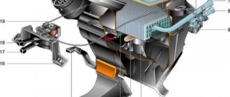
Let's look at the elements of the most common model D5WZ
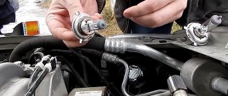
Glow plug - necessary to ignite the fuel at the beginning of the heater start-up cycle and to burn off residual fuel during purging after shutdown.
Malfunctions:
1. The filament burns out inside and the spark plug “breaks”.
2. The glow of the spark plug is insufficient to ignite fuel vapors.
A flame sensor is a means of monitoring the presence of flame inside the combustion chamber. The nominal resistance at 20ºC should be 1 kOhm.
Possible malfunction:
The sensor resistance exceeds the permissible threshold values.
Coolant temperature sensor and overheating sensor - serve to monitor the temperature of the heat exchanger.
The nominal resistance of the sensors at 20ºС should be 12 kOhm.
Possible malfunctions:
1. Resistance (reading) is outside the operating range.
2. Incorrect readings of the sensor(s), for example: the coolant temperature is 50ºС, and the resistance of the sensor(s) corresponds to a reading of 80ºС.
Electric fan . Purpose: pumps air into the combustion chamber.
Possible malfunctions:
1. Wear of bearings on the electric fan shaft.
2. Wear of brushes and rotor.
3.The plastic brush holder inside melts.
grid allows fuel vapors (rather than solid drops) to be supplied to the spark plug and into the combustion chamber.
Main faults:
1.Clogged with impurities in the fuel (poor quality fuel).
2. It burns out over time until it reaches a through hole (high-quality fuel).
The combustion chamber - burner, flame tube - is the direct place of combustion of the combustible mixture.
Possible malfunction: over time, after heating, the insides of the burner peel and deform, which is why the flame breaks out during ignition or during operation (unstable combustion).
Control unit - controls the operation of all elements and the entire heater.
Malfunctions:
1. Diagnoses an error based on an element that is in fact absolutely fine.
2. Not diagnosed.
Reasons: oxidation, corrosion, paths on the board are destroyed (vibration, heating-cooling cycles)
Errors in Eberspacher liquid heaters
| 00 | No mistakes | |
| 04 | Short circuit | Short circuit in control unit, accessory terminal |
| 05 | Short circuit | Short circuit in the control unit, security system terminal |
| 09 | Disabling ADR | Trip due to signal polarity reversal |
| 10 | Overvoltage - heater shutdown | The increased voltage on the control unit remains for at least 20 seconds. Continuously |
| 11 | Low voltage - heater shutdown | The reduced voltage on the control unit remains for at least 20 seconds |
| 12 | Overheating on the overheating sensor | Temperature at overheating sensor > 125°C. |
| 13 | Overheating on combustion sensor | The combustion sensor detects exceeding the permissible temperature on the heat exchanger |
| 14 | Possibility of overheating detected | Temperature difference between overheating sensor and temperature sensor > 25⁰С |
| 15 | Blocking | The heater has overheated more than 10 times |
| 17 | Overheating detected - emergency shutdown | Temperature at overheating sensor > 130°C |
| 19 | Insufficient energy to ignite | Contact the service center |
| 20 | Candle - break in the circuit | Contact the service center |
| 21 | Spark plug - short circuit | Contact the service center |
| 22 | Spark plug - short circuit to (+) | Contact the service center |
| 25 | Diagnostic cable short circuit | Contact the service center |
| 30 | The air intake fan motor speed is outside the permissible limits. | The impeller is stuck (ice, dirt, shaft wear...). |
| 31 | Intake fan motor - open circuit | Contact the service center |
| 32 | Intake fan motor - short circuit, overload | Contact the service center |
| 33 | Deviation of the supercharger speed by more than 10 from the permissible value for more than 30 seconds | Supercharger does not rotate Contact the service center |
| 34 | Intake fan motor - short to (+) | Contact the service center |
| 38 | Car fan relay - open circuit | Contact the service center |
| 39 | Car fan relay - short circuit, overload | Contact the service center |
| 41 | Water pump - open circuit | Contact the service center |
| 42 | Water pump - short circuit, overload | Contact the service center |
| 47 | Dosing pump - short circuit, overload | Contact the service center |
| 48 | Fuel pump circuit open | Contact the service center |
| 49 | Fuel pump circuit short to (+) | Contact the service center |
| 50 | Exceeding the allowed number of starts | Blocking of the control unit due to exceeding the permissible number of startup attempts |
| 51 | Cold purge time exceeded | When turned off, during the purge stage, the combustion sensor shows a temperature of more than 70°C for more than 240 seconds. If the error remains, contact the service center. |
| 52 | Exceeding the safe time limit | The presence of a flame is not detected during the startup phase |
| 53 | Stopping the torch burning at the “high” operating stage | We contact the service center. |
| 56 | Stopping the torch burning at the “small” operating stage | We contact the service center. |
| 60 | Temperature sensor circuit open | We contact the service center. |
| 61 | Temperature sensor circuit short circuit | We contact the service center. |
| 64 | Open circuit of the combustion sensor | We contact the service center. |
| 65 | Flame sensor circuit short circuit | We contact the service center. |
| 71 | Overheat sensor circuit open | We contact the service center. |
| 72 | Overheat sensor circuit short circuit | We contact the service center. |
| 90, 92-103 | The control unit is faulty | We contact the service center. |
| 91 | Presence of external electrical interference | We contact the service center. |
LiveInternetLiveInternet
This manual is a guideline only and applies to the 2013 Ssang Young Kyron Diesel. It is assumed that no technical modifications have been made to the vehicle through the installation of additional equipment that could affect the installation procedures described below. Otherwise, depending on the modification and equipment, the installation procedure may differ from that described in this manual. INFORMATION ABOUT THE LEGALITY OF USE OF THE INSTRUCTIONS The installation instructions are valid for cars whose engine capacity and gearbox correspond to the data presented in the table. Vehicle specifications, options. Engine capacity kW/hp Gearbox 1998 cm3 104/141 automatic transmission ATTENTION! These installation instructions do not apply to right-hand drive vehicles. Installation is not recommended for vehicle models not listed in this manual. FIRST START OF THE HEATER After installing the heater, check that all wires, clamps, and electrical connections are well installed and secured. Follow the vehicle manufacturer's instructions when filling the hydronic heating system. Remove air from the liquid heating system. During the first start-up, check the fluid circuit and fuel supply pipes for leaks. If malfunctions occur with the heater during the first start-up, then it is necessary to use diagnostic equipment to troubleshoot problems. HEATER KIT FOR INSTALLATION Qty. Name Catalog number 1 D5WS with installation kit 25 1 Bushing (plastic passage) 20 1 Corrugated hose 10 1 Fiberglass sleeve 25 1 Liquid hose 20 1 Control device* 1 Fuel adapter. tee** 25 2 pcs. Brass bushings d=8mm** 22 1 Fuel tee D=10mm** 262 31 152 0.2 m. Rubber fuel. hose d=9mm** 360 75 404 4 Clamps** 10 * - the control device is optional. ** - these items are not required if the fuel connection is made using a standard fuel intake. INSTALLATION TIME The recommended time for installing the heater is 10 n/h. ATTENTION! This installation kit contains all the necessary equipment to install the heater on the vehicles specified in this manual. SPECIAL TOOLS REQUIRED Torque wrench (5...50 Nm) Pliers for standard clamps Terminal crimping tool TIGHTENING TORQUES If the tightening torque is not specified, tighten the threaded connection according to the table. Type of threaded connection Tightening torque M6 10 Nm M8 20 Nm M10 45 Nm
INSTALLATION LOCATION
Save to Album INSTALLATION LOCATION
Hydronic is installed at the front, inside the engine compartment in front of the radiators on a reinforcing beam. 1. Heater 2. Fluid pump 3. Heater muffler 4. Air intake 5. Control device 6. Relay 7. Fuses 8. Dosing pump 9. Fuel intake
HEATER INSTALLATION
PREPARING THE CAR FOR INSTALLING A HEATER
Save to Album PREPARING THE CAR FOR INSTALLING A HEATER
Disassemble the plastic trim inside the car to gain access to the electrical harness for the climate control panel. Remove the decorative plastic panel of the steering column space to connect the electrical harness of the control device. To gain access to the fuel pump module, the fuel tank must be removed.
Save to Album PREPARING THE CAR FOR INSTALLING A HEATER
Remove the headlights and front bumper of the car. The heater is installed in front of the radiators on a reinforcing beam behind the front bumper. Secure the universal bracket into the prepared holes on the amplifier using M6 bolts and threaded rivet bushings (top points); bolts and nuts (lower points) as shown in the photo. Install the heater onto the mounting bracket using the special bolt from the mounting kit.
AIR SUPPLY TO THE COMBUSTION CHAMBER AND EXHAUST GASES DISCHARGE
Save to Album SUPPLY OF AIR TO THE COMBUSTION CHAMBER AND EXHAUST GASES
Install the muffler using the bracket on the bottom of the reinforcing beam. From the exhaust pipe included in the standard installation kit, cut two parts in place and secure them with clamps to the muffler and heater pipes. WARNING Due to high exhaust temperatures, keep the exhaust pipe clear of hoses, electrical harnesses, and other vehicle components. If necessary, use a thermal insulation sleeve (25 1676 80 0001). Secure the air intake pipe and exhaust pipe with the clamps included in the standard installation kit. The exhaust pipe outlet should not be directed towards the direction of vehicle movement, as well as components and assemblies that may be damaged by high temperatures of exhaust gases. When the exhaust pipe passes through a plastic boot, it is recommended to use a heat-insulating sleeve (20 1549 65 00 02). At the lowest point of the air pipe, it is recommended to drill a hole with a diameter of 4.5-5 mm to drain condensate. Secure the air intake pipe with plastic ties. The outlet of the air pipe should not be directed towards the vehicle.
FUEL SUPPLY
Save to AlbumFUEL SUPPLY
DANGER
Before installing the fuel system, remove the fuel tank cap and ventilate it. After installation, close it. Remove the fuel tank and remove the fuel pump module. Disconnect electrical and fuel connectors. Drill a hole with a diameter of 8-9 mm in the fuel pump module. Bend the fuel intake in place, install it in the fuel pump module, having first shortened it to the required length. Given the depth of the fuel tank, it is recommended to leave approximately 25mm from the bottom. Please note that the fuel pick-up must not interfere with moving parts of the fuel pump module such as the fuel level sensor float, etc. ATTENTION! The length of the fuel line must not be increased in any way! Install the fuel pump module back into the tank, connect the standard fuel lines and electrical connectors. Install a 4×2 mm (blue) fuel line onto the fuel intake tube using a rubber hose l=50mm. Secure the connection with the clamps included in the installation kit. In this configuration, it is possible to connect the fuel line to the vehicle’s fuel line without dismantling the fuel tank. To do this, use a fuel tee (d=6, D=10mm) and a fuel line adapter. The insertion should be made in a place as close as possible to the fuel tank. ATTENTION! The fuel tee and adapter are not included in the universal installation kit. ATTENTION! The length of the fuel line must not be increased in any way! Install a 4x2 mm fuel line (blue) onto the tee through the fuel adapter. Secure the connection with the clamps included in the installation kit. The insertion point into the standard fuel line should be reinforced with brass bushings. When installing the fuel tee, the permissible installation position must be observed. Secure the metering pump with an M8 bolt into the standard threaded bushing. When installing the dosing pump, the permissible installation position must be observed. CAUTION The metering pump should always be positioned with the discharge side up and upward, as shown in the figure. Any angle greater than 15° is acceptable, but installation at an angle of 15 to 35° is preferred. 1. Installation at an angle of 0° - 15° is not allowed. 2. Installation at an angle of 15° - 35° is preferred. 3. Installation at an angle of 35° - 90° is allowed. ATTENTION! When connecting fuel lines and hoses, always connect them end to end to avoid the possibility of bubbles forming. 1 – correct; 2 – incorrect. Install the fuel lines to the metering pump on the suction side (blue) and discharge side (white) using rubber hoses and clamps. Lay the 4x1.5 fuel pressure line together with the cable harness from the metering pump to the heater. The power supply harness for the metering pump can be shortened locally and connected to the connector on the heater using the crimp terminals included in the kit.
CONNECTION TO THE COOLING SYSTEM
Save to AlbumCONNECTION TO THE COOLING SYSTEM
CAUTION Before connecting to the vehicle's cooling system, the coolant must be drained. When installing liquid hoses, avoid chafing. Install the liquid pump with a bracket into the standard hole in the arch of the right front fender and secure it with an M6 bolt and nut.
Save to Album Schematic diagram of pump connection and installation
Schematic diagram of connecting the heater to the liquid system of the car. 1. Hydronic heater. 2. Liquid pump. 3. Connecting elements. 4. Interior heater heat exchanger. 5. Car engine.
1. Liquid pump. 2. Corner holder. 3. Fasteners.
Connect the heater liquid pipes to the vehicle's cooling system in accordance with the diagram shown in the figure. ATTENTION! The direction of coolant flow must be taken into account. If necessary, it is recommended to study the technical documentation for this car model. The connection of liquid pipes should be made using brass bushings and metal clamps included in the installation kit. If necessary, use corrugated hose.
INSTALLATION OF ELECTRICAL EQUIPMENT
Save to AlbumElectrical diagram of climate control and ventilation control
CAUTION Wire colors and pin numbers may not match! Read the technical documentation for this vehicle (electrical circuit diagrams for climate control and ventilation) Legend: Relay (2.5.7) – Interior fan control relay, included in the standard heater installation kit; Fuse (2.7.5) - Fuse for the vehicle cooling system fan, included in the standard heater installation kit; (2.1) – Heater control unit;
Save to AlbumElectrical wiring installation
CAUTION Before installation, remove the fuses from the holder. Install the relay block and fuse block onto the bracket included in the installation kit. Remove the fuses. Connect the red (+) and brown (-) heater wires to the battery. It is allowed to connect the brown (-) wire of the heater to the standard ground connection point on the car body. Route the heater electrical harnesses into the vehicle interior. If necessary, use a bushing. Strip the red wire in the gray 16-pin connector located on the back of the interior heater control panel and make electrical connections in accordance with the diagram shown in the figure. It is recommended to use the electrical connectors included in the installation kit. Insulate the connection
INSTALLING THE CONTROL UNIT Easy Start T
Save to Album INSTALLING THE CONTROL DEVICE Easy Start T
Lay the control cable to the Easy Start T installation location. Measure and cut off the excess length of the cable wires. Crimp the wires with the contact terminals from the Easy Start T kit. Install the block from the Easy Start T kit onto the contacts of the wires of the control cable from the heater
Save to AlbumFuse block.
Install fuses and relays into holders
COMPLETION OF INSTALLATION
Connect the car battery. Install all dismantled parts. Check that all wires, clamps, and electrical connections are well installed and secured. Remove air from the liquid cooling system and check the tightness of all connections. It is recommended to fully comply with all vehicle manufacturer's instructions when filling and bleeding the liquid heating system. Secure all loose wires with fixing tapes. Follow the instructions and safety regulations contained in the technical description. ATTENTION! For the Hydronic to function correctly, before turning off the ignition, the interior regulator must be set to the High position, the air damper position must be in the “window blower” position.
This installation manual for the Eberspacher Hydronic D5 WS engine fluid preheater (Eberspacher Hydronic 5 kW, spaced type) describes the installation diagram, the so-called, a kind of installation map, with pictures, photographs and diagrams. If desired, it is also possible to install any other equipment, an engine heater that has similar technical data, for example Webasto Thermo Top Evo 5D (Webasto Thermo Top Evo 5)