How to connect a subwoofer via a bridge
The bridge amplifier circuit is designed for multi-channel amplifiers.
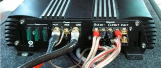
To connect a sub bridge you need two or four channels. Before trying to bridge the amplifier, you should carefully read the operating instructions. There are models of low-frequency amplifiers that do not require this type of connection, as this can lead to their breakdown. This information is always available in the amplifier's technical description. Bridging a subwoofer to a two-channel amplifier is simple. On the rear wall of the amplifier there are several terminals that are designed to supply power, connect the control circuit and speaker systems. The speaker terminals are marked with the letters “L” and “R”, which correspond to the left and right channels. The polarity must be marked there. Above the terminals there is the inscription “BRIDGEMODE” and the points to which the speaker should be connected are indicated.
How to bridge a subwoofer
Connecting a subwoofer with a bridge does not require installing any jumpers and the speakers are connected to the appropriate terminals. When organizing a bridge connection, you should remember that not every two-channel amplifier is capable of operating a low-impedance load.
If the resistance of the dynamic head is 4 Ohms, then when bridged, each channel of the low-frequency amplifier will operate at half the load, that is, each channel when bridged is 2 Ohms. This load is safe for almost all car amplifiers.
But some bridge connection options can be dangerous for sound-reproducing equipment.
Connecting a 2-channel amplifier to a subwoofer with a bridge
When connecting a subwoofer in bridged mode with two voice coils, some difficulties may arise. If the sub has two windings of 2 ohms, then with a parallel connection the total resistance will be equal to 1 ohm. This connection is often used by car enthusiasts to obtain maximum subwoofer power. Here you need to take into account that with a bridge connection, each channel will operate at a load of 0.5 Ohms, and not a single car multi-channel amplifier can withstand such a value. Thus, when connecting a two-coil subwoofer with 2 Ohm windings to the bridge, they can only be connected in series. Having a total resistance of 4 ohms, you don’t have to worry about the failure of the amplifier, since with a bridge connection the resistance will be equal to 2 ohms per channel, which is quite normal. Connecting a subwoofer with a bridge to a two-channel speaker, subject to the rules, will provide an increase in output power from 2 to 2.5 times.
How to connect a sub in bridge mode
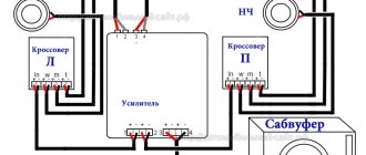
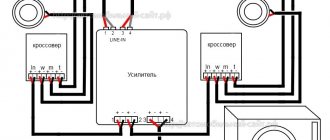
The bridge subwoofer connection circuit can be used not only with two-channel amplifiers, but also with four-channel equipment. Connecting a four-channel amplifier with a bridge to a subwoofer has no differences. The woofer is connected between the plus of one channel and the minus of the other. The remaining two channels are used to connect the front speakers. Thus, one four-channel unit can provide high-quality sound to a car interior. When organizing a bridged connection of a subwoofer, two conditions must be met:
When connecting two subwoofers, polarity is very important. If the speakers are connected incorrectly, then when sound is played, the cone of one speaker will move forward, and the cone of the second will move in the opposite direction. There will be no damage to the audio system, but the sound quality will be poor.
Scheme development
The connection diagram depends on the number of amplifier inputs, the location and power of the speakers, and the presence or absence of a subwoofer.
Power amplifiers are:
- two-channel, designed to connect only a pair of speakers;
- four-, used to connect two speakers and a subwoofer or four (there is also a daisy chain connection scheme for four speakers and a subwoofer);
- six-, used for a standard connection of four pieces and a subwoofer.
It is also important to consider the rated power (W, W) and the resistance of all connected equipment (Ohm). They can be found either on device labels or in technical documents. The total connection resistance should not exceed the maximum permissible standard.
There are three ways to connect speakers to an amplifier.
- Sequentially—speakers of the same type are alternately connected to each other and then to the device.
- Parallel - performed by a polar connection directly to the outputs of the device, while their resistance and power may differ.
- Series-parallel - used in cases where it is necessary to connect two columns with the same resistance and additional ones with other parameters.
Connecting a subwoofer to an amplifier with a bridge
A bridge connection of a subwoofer can be organized on two separate amplifiers. If the design allows such a connection, then there are “Master/Slave” or “Master/Slave” switches on the case. Before connecting, you should select which of the two blocks will perform the corresponding function and set the switches to the desired positions. The “leading” block, using interblock cables, is connected to the “Tulip” connectors to a music center or car radio. The picture shows the connection of two amplifiers using a bridge circuit. a music center or car radio is connected.
Next, from the output connector, a single interconnect cable, the signal is transmitted to the “Slave” unit. In this case, all control is carried out from the “Master” block. Some systems allow operation in bridge mode, but there are no corresponding switches on the blocks. In this case, two connectors are installed on the case - “BridgeInput” and “BridgeOutput”. To organize the bridge mode, you need to connect the “BridgeOutput” socket of the master unit to the “BridgeInput” socket of the slave device.
How to bridge a subwoofer to an amplifier
This connection of the subwoofer with a bridge to the amplifier provides a twofold increase in output power due to the amplifier operating at a reduced resistance of the speaker voice coil. With a winding resistance of 4 Ohms, each block will be loaded with a load with a resistance half as much. To connect a passive subwoofer, you need to use special speaker cables made of natural copper. Copper-clad aluminum or steel wires should be avoided. There is no need to buy both the cheapest and the most expensive cable. In the first case, it is a low-quality product, and in the second, it is a waste of money.
Source
Connection diagram
Connecting the amplifier begins with laying the power cables and the control cord leading to the head speaker unit. For power supply, a copper cable with insulation that does not deteriorate when exposed to negative temperatures is used. The wiring is routed under the floor and sill trims, and then routed to the battery installation location (under the hood or in the luggage compartment). It is recommended to connect the negative and positive power cables to the battery. Additionally, a capacitor is provided in the circuit to smooth out voltage drops.
The positive cable is equipped with a special fuse located at a distance of 400-500 mm from the battery terminal. The rating of the insert depends on the parameters of the standard protective devices located in the amplifier block. For example, when using a fuse rated for a current of 40 A in an amplifier, the rating of the protective unit in the power circuit should not exceed 50 A. Metal crimped tubes or soldering are used to connect electrical wiring components; twisted wires do not provide unreliable contact and are susceptible to oxidation.
Wiring
The wires are laid in such a way as to avoid damage and kinks. To do this, the wiring is placed in a flexible plastic tube of suitable diameter and laid under the floor covering.
To protect and shield speaker cables, they can be routed inside a split metal tube that can be grounded.
How to connect a subwoofer
The low-frequency loudspeaker is connected by a bridge to the outputs for rear speakers. The negative cable is connected to the negative terminal of one output, and the positive signal comes from the positive terminal of the opposite channel. Front channels are used to connect the remaining speakers, which are connected in parallel or in series. The connection diagram depends on the resistance rating of the coils and the characteristics of the amplifier unit.
In the connection circuit of a 4-channel amplifier and subwoofer, it is possible to introduce an additional low-frequency speaker (with identical characteristics), which is switched by a bridge to the front channels. In this case, an additional amplifier unit is introduced into the car's acoustic system, servicing loudspeakers that reproduce medium and high frequencies.
External amplifiers are designed to increase the volume and quality of sound transmitted by the radio. A bridged 4-channel amplifier is designed to connect external speakers and a subwoofer for maximum sound power. The design of the amplifier allows you to configure the harmonious parameters of the combined sound of standard loudspeakers and a subwoofer.
How to connect a four-channel amplifier
It is necessary to check whether the car audio amplifier is capable of functioning in bridge mode before connecting 4 speakers to it. Otherwise, the sound will be distorted or the device will quickly fail after switching on due to overheating caused by excessive load. If the four-channel amplifier is connected incorrectly, the speakers will reproduce not the sum, but the difference of the stereo channel signal.
The resistance of the speakers and subwoofer connected to the same channel should not be lower than the operating resistance for which the amplifier is designed. Otherwise, the device will also be overloaded, which will lead to overheating and rapid failure of the device. The choice of connection diagram depends on the availability and number of speakers.
How to setup
On the front panel of the 4-channel amplifier there are controls and switches that set various parameters. You must make sure that the power indicator is on and the protection alarm is not on before setting up the amplifier. Otherwise, the problem is detected and corrected.
The first stage of setting up a bridge amplifier is to adjust the input level necessary to match the radio. This indicator is set using a regulator or switch. If the radio is connected to high-level inputs, then this control is first set to the 6 V position. Then the lowest input level is set at which the sound remains undistorted when the volume control of the radio is in the high position. After this, the amplifier is configured for all other parameters.
If a subwoofer is connected to the device, you must turn on the low-pass filter, if it is provided for in the amplifier design. The cutoff frequency is initially set at 65-85 Hz and then adjusted more subtly by ear to achieve the desired sound quality depending on the size of the subwoofer and where it is installed.
Some devices have additional controls for more precise adjustments. For example, using an ultra-low-pass filter, you can filter out sounds below 20 Hz to reduce unnecessary load on all speakers and thereby optimize the power consumption of the amplifier.
Connection diagram of the subwoofer to the standard radio
The connection diagram looks elementary:
— GU (wires going to the rear speakers are designated in the diagrams as RR+- and RL+-) — signal converter — external amplifier.
If you use high-level inputs on the amplifier, then it’s even simpler:
- GU - amplifier. On the amplifier, the high level inputs are labeled Hi Level Input, Hi Input, or Speaker Level Input.
Connection diagram
The connection diagram for a 4-channel amplifier requires reliable power supply, which is supplied from the positive terminal of the battery. The cables are connected through a fuse insert; the rating of the protective element is 5-10% higher than the ratings of the factory fuses in the amplifier housing. The cable cross-section is selected according to the table depending on the power consumption. When using a thin cable, overheating and destruction of the insulation occurs, leading to a short circuit and ignition of the structure or vehicle.
The negative signal is supplied through a connection to the ground bolt welded to the car body panels. A lug is put on the cable, which is then pressed with a nut. On used domestically produced cars, it is recommended to remove power from the negative terminal of the battery, since corrosion on the surface of the bolt increases the contact resistance and degrades the power supply to the equipment.
To automatically turn on the amplifier, a copper cable (with a cross-section of up to 1 mm²) is used, coming from the REM connector of the head unit. After turning on the radio, a control signal is supplied to the amplifier, activating the power circuits. To transmit the audio signal, RCA standard cables are used, equipped with a screen to protect against interference. Special metal tips are placed on the ends of the cords to ensure reliable contact. Interconnect cables must not be laid near power wiring due to interference.
Grounding
One end of the wire is connected to the negative terminal of the car amplifier, and the other is inserted between the bracket or bar securing the device and the floor of the body.
After this, the connection point is treated with WD-40 to increase reliability and protect against corrosion, and the nut or bolt is tightened.
To avoid interference in the speakers, the body of the device should not be allowed to come into contact with the body of the car. Otherwise, ground loops will form, which will lead to unpleasant interference. To isolate the housing from the car body, you can place a strip of rubber under the mounting bracket.
Connecting an amplifier with a bridge
Today we will look at such an interesting possibility of increasing power as connecting an amplifier with a bridge and how to connect 2 amplifiers in a similar way. In this mode, one channel works as a plus (+) and the other as a minus (-) , which increases the power by 2-2.5 times. The result will depend on the system power supply and amplifier model.
Most often, this operating mode is used for a subwoofer, as the most power-demanding element. You can connect either two amplifier channels or two separate monoblocks to the bridge.
Bridge connection of two channels
So, to bridge two channels of one amplifier, you need to take a plus (+) from one and a minus (-) from the other. For two and four channel amplifiers, the circuits are no different.
Bridge connection of 2 channels
Bridge connection of 4 channels
In principle, connecting an amplifier with a bridge is not a difficult operation; it does not require any jumpers or additional connections. Connect the positive wire from the subwoofer to the positive terminal (+) of one channel, and the negative wire, respectively, to the negative (-) terminal of the second.
Make sure your amplifier is bridged first.
Parallel-serial connection diagram
This is the most popular connection method, as it allows you to regulate the power supplied to the device and avoid overloading it. This results in high-quality sound. This connection scheme combines both methods.
Step-by-step instructions for connecting four speakers to two channels of the device.
- The negative terminal of speaker 1 is connected to the positive terminal of speaker 2.
- Negative contact 3 is connected to positive
- Positive contact 1 is output to a common positive channel with positive contact 3.
- Negative contacts 2 and 4 are connected to a common negative contact.
- The derived common channels are connected to the amplifier, taking into account the polarity of the contacts.
In the same way, subwoofers can be connected to this system if two-channel equipment is used. With four channels, the subwoofers are connected separately by a bridge.
Watch the connection video
Setup Instructions
The amplifier is configured in accordance with the recommendations set out in the operating instructions. To adjust the parameters, buttons and rotary switches are used, covered with a protective panel. Rotating correctors are recessed into the body, which reduces the likelihood of accidental position changes. To rotate the element, it is recommended to use a flat blade screwdriver.
A control diode of the power supply is installed on the equipment case; further adjustment of the device is allowed only when the green lamp is turned on. When using standard factory settings of the equipment, the sound picture is blurry. Adjusting the parameters allows you to highlight low and high frequencies, as well as reduce sound distortion.
Amplifier setup for four speakers without subwoofer
After completing the connection of the four-channel amplifier and checking the operation of the electrical circuits, you need to configure the acoustics according to the following method:
What do you need
To carry out the work yourself, you will need consumables and tools. A two-channel amplifier is installed when using:
- Cable with a cross-section of at least 2.5 mm2. The amplifier is often installed in the luggage compartment, so a long cable length will be required. It is not recommended to use low-quality material, because... It will not last for a long period and may cause interference.
- To protect the connections and the wire, insulating material is required: insulation, corrugated plastic tube.
- The quality of the connection can be improved by using special adapters. They allow, if necessary, to dismantle individual parts.
When working, a knife, a multimeter, a set of screwdrivers and some other tools are used. The amplifier is located in the luggage compartment. It is recommended to purchase or make a plastic container for it, which will protect the device from moisture and dirt.
Laying wires in the cabin
To connect a two-channel amplifier, you need to lay the cable around the cabin. In Supra and some types of cars, fastening is carried out using bolts and other elements. The main recommendations for carrying out such work are as follows:
Are you a car driver?! Then you can take this simple test and find out. Go to test »
- All finishing materials are first dismantled. If after disassembly it turns out that there is moisture under the trim, then you need to check the integrity of the body and protect it from water. High humidity can reduce system reliability.
- The interconnect cable is laid away from the power lines. Otherwise, there is a possibility of interference.
- In places where the cable comes into contact with the edges, it is recommended to use a corrugated tube. Minor vibration can cause the insulation to rub.
- To turn on the device, a separate power cable is laid. It is not recommended to connect directly to the battery, because there is a possibility of complete and rapid discharge.
- It is planned to install a safety element in close proximity to the power source.
The cable connection is made using soldering. It is recommended to clean the contacts first.
Amplifier power
The amplifier is installed in most cases in the trunk. This point complicates the installation of the cable from the power source. Among the features are the following:
- It is recommended to use a larger cable. It will be able to last for a long period of time.
- Provides for the presence of a key in the system.
- The power supply is routed away from the interconnect network. In this case, it is recommended to use the shortest path and also reduce the number of connections.
- A fuse is installed in the immediate vicinity of the power source. It is selected taking into account the power of the device; it is recommended to choose with a reserve.
When installing a fuse, it should be protected from environmental influences.
Grounding organization
The operating instructions for all amplifiers indicate that the device must be grounded. The recommendations are as follows:
- A cable with a thickness of at least 2.5 mm2 is used. Otherwise, there is a possibility that the core will overheat.
- For fastening, you can use any fastening element located in the immediate vicinity.
The wire must be protected from environmental influences.
Good nutrition is the key to success
The amplifier connection procedure begins with the power wires. Wiring is the most important element of a car audio system; the volume and sound quality depend on it. Amplifiers need a stable power supply, otherwise the power will not be enough and the sound will become distorted. To understand why you need to pay attention to the quality of wiring and how it affects the sound reproduced by a loudspeaker, you need to know what a music signal is.
Some suggest that it represents a sine wave, however, the musical sinhala is characterized by a large difference between the normal and peak value. If sharp signal bursts are not important for car speakers, then in the case of an amplifier the situation is completely different. If the signal exceeds the permissible power for even a second (or even a millisecond), then these “anomalies” will be audible even to those who cannot boast of a good ear for music.
If the car amplifier is connected properly, the signal will flow through the wires undistorted. Carelessly done work or incorrectly selected wire cross-section will result in the sound being more compressed, rough and sluggish. In some cases, wheezing may also be clearly audible.
How to choose a wire cross-section?
Wire is the most common metal with a certain level of resistance. The thicker the wire, the lower the resistance of the wire. To avoid sound distortion during large voltage fluctuations (for example, when playing powerful bass), you must install the correct gauge wire.
It is worth noting that the cross-section of the positive cable should not be larger than the negative one (the length does not matter).
An amplifier is considered to be a rather electrically intensive device. For its effective operation, high-quality grounding is necessary so that it is possible to receive the necessary energy from the battery. To choose the correct wire cross-section, you need to make some calculations. First, look at the instructions for the amplifier (or directly at the box from the manufacturer, if there is no documentation, use the Internet) and find the rated power value (RMS) there. Rated power is the signal power an amplifier can deliver over an extended period of time to one channel of 4 ohms.
If we consider four-channel amplifiers, they usually have a power of 40 to 150 watts per channel. Let's say that the amplifier you purchased produces 80 watts of power. As a result of simple mathematical operations, we find out that the total power of the amplifier is 320 W. Those. How did we calculate this? It’s very simple to multiply the rated power by the number of channels. If we have a two-channel amplifier with a rated power (RMS) of 60 W, then the total will be 120 W.
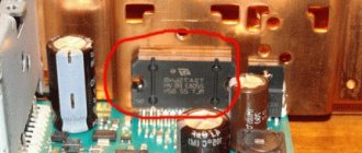
Circuit diagram of CALCELL POP-80.4
The following are schematic diagrams of the main components of the amplifier. When you click on the picture, the diagram opens in a new window in the original resolution.
Amplifier converter (inverter) circuit.
All amplifiers are powered by an inverter based on the TL494CN . The inverter converts +12 volt DC voltage from the car battery into bipolar ±28 volt voltage, which is necessary for the operation of the amplifiers. Read more about the design of the inverter (converter) here.
Amplifier input filters.
This device consists of 4 amplifiers identical in circuit design. At the input of each amplifier there is an input filter based on operational amplifiers of type BA4558 (in the diagram U101, U102, U103, U301, U302, U303).
Circuit of preamplifiers and UMZCH. Channel A and B.
Bipolar transistors are used as output amplification transistors in the UMZCH, or rather the complementary pair 2SC4467/2SA1694 (in the diagram Q111, Q211/Q112, Q212).
Attention! There are errors in the diagram. The bases of transistors Q112, Q212, Q312, Q412 are connected to the emitters of transistors Q110, Q210, Q310, Q410, and not to the collectors!
Good day everyone!
I'm in a good mood and I'm ready to share my joy with you
Source
Connecting an amplifier with a bridge
Today we will look at such an interesting possibility of increasing power as connecting an amplifier with a bridge and how to connect 2 amplifiers in a similar way. In this mode, one channel works as a plus (+) and the other as a minus (-) , which increases the power by 2-2.5 times. The result will depend on the system power supply and amplifier model.
Most often, this operating mode is used for a subwoofer, as the most power-demanding element. You can connect either two amplifier channels or two separate monoblocks to the bridge.
Bridge connection of two channels
So, to bridge two channels of one amplifier, you need to take a plus (+) from one and a minus (-) from the other. For two and four channel amplifiers, the circuits are no different.
Bridge connection of 2 channels Bridge connection of 4 channels
In principle, connecting an amplifier with a bridge is not a difficult operation; it does not require any jumpers or additional connections. Connect the positive wire from the subwoofer to the positive terminal (+) of one channel, and the negative wire, respectively, to the negative (-) terminal of the second.
Make sure your amplifier is bridged first.
Important points
- Make sure your amplifier supports bridged connections.
- Make sure your amplifier or amplifiers support the intended impedance.
- Keep in mind that when connecting two amplifiers to a bridge, the Slave's protection may be disabled. Watch him closely.
- Do not connect different channels/amplifiers separately to the coils.
A simple and clear video on how to connect two amplifiers to a bridge:
Happy connections!
How to connect two amplifiers with a bridge
Master/Slave
Amplifiers designed for this connection have MASTER/SLAVE switches. Therefore, with a bridge connection, one of the amplifiers will be the master ( Master ) and the second will be the slave ( Slave ), set the switches in this accordance. It is to the Master that the interconnect cables (tulips) from the radio are connected, and from it, through a mono connector, the signal is transmitted to the Slave (with a single interconnect). This is done so that all settings and control are carried out from one monoblock - from the Master, that is, gain, filters, subsonic, etc. will be exhibited only there. There is no need to take Y splitters to try to plug interconnects into the Slave as well.
If the manufacturer declares that the amplifier can operate in a bridge, but there are no Master / Slave switches, then it will have two sockets with similar names - Bridge Input and Bridge Output . In this case, use the Bridge Output jack on the master amplifier and connect it to the Bridge Input jack of the slave amplifier.
Connecting speaker wires
Here, be careful and do not confuse anything: we connect the negative connectors of the two amplifiers to each other; then we connect the plus (+) of the Master to the plus of the subwoofer, and the plus of the Slave to the minus of the subwoofer !
Yes, there are two positive wires going to the subwoofer, no need to strain - everything is correct. The fact is that a direct signal is supplied to the input of one amplifier, and for the second the signal is turned 180 degrees. Therefore, at the output of one the positive potential increases, and at the output of the second it is the same but negative. The increase in power occurs because the amplifiers or channels (in the case of using one wuxia) operate at reduced resistance. For example, if the sub is connected to 4 ohms, then each amplifier or channel operates at 2 ohms, etc.
How to set up a subwoofer in a car
Setting up the subwoofer should be done while designing the speaker box. The main role here is played by the parameters of the speaker, which determine the boundaries of its functioning in the acoustic design. If you have a dilemma about how to set up a sub in a bass reflex enclosure, it is recommended to install the port both higher and lower, depending on your favorite type of music. And for a device in a factory frame, connecting a subwoofer with a bridge is limited, but with a well-chosen circuit it is more than possible to achieve good sound.
As a backup option, use special applications for your phone (Subwoofer Bass).
Setting up the LPF lowpassfilter filter
Nowadays, a classic LPF filter is almost always present on a subwoofer. This type of filter allows you to select the threshold at which high frequencies begin to be blocked, which allows you to simply mix the signal with other speakers. To properly configure the filter, you need to know in advance how this is done.
First, you need to make sure that the initial parameter was not too high, and that the woofers on the subwoofer do not overlap: this risks leading to unnecessary emphasis on one frequency level (about 120 Hz) and unclear sounding of the acoustics. But if connected too low, there may be a large gap between the car signal and the speakers.
At the start, it is recommended to set the LPF filter at a frequency of 80 Hz, and then conduct a sound test and change it as desired until it sounds as the owner requires. It’s better to deactivate the filter on the radio. When there is a chance to apply LPF on the main device, you need to activate it only there. You should not run the filter at the same time as the amplifier.
Setting up a subsonic
Subsonic is an infrasonic format filter that can block ultra-low frequencies that always appear in some compositions. These frequencies cannot be heard at a typical threshold because they operate below the threshold of human hearing. But when they are not initially trimmed, the device will consume additional energy through startup relative to the all-in-one.
You can set up an active subwoofer in your car, automatically blocking infra-low frequencies - the device will be able to effectively reproduce only those that are present within the established limits. Thus, unpredictable failure of a two-coil subwoofer after accelerated movement of the diffuser is eliminated.
The speaker will try to repeat frequencies that lie outside the perceptible range (20-25 Hz and below). Then the diffuser will speed up, which risks causing the two-coil device to exit near the gap and result in damage. Subsequently, the quality of reproduction of the required bass range increases in quality, in addition, the volume increases.
To tune the subsonic, you should set it at least 5 Hz below the level of the bass reflex port. To do this, turn on the switch and move it to the desired data. When the subwoofer is configured correctly, passengers in the car will not hear it, since it should not provoke interference with the central signal.
Setting the input sensitivity GAIN
Sometimes car owners do not know how to correctly adjust the input sensitivity. This value demonstrates how it is possible to apply a signal to the input in order to result in rated power. It should be adjusted for the incoming flow voltage. It is worth adjusting the input sensitivity correctly to prevent accidental signal changes, distorted sound, or other problems with the speakers.
To change the GAIN values, you will need:
- digital voltmeter, which can measure AC voltage values;
- test CD or file where a sine wave is saved with an initial level of 0 decibels (it is important not to use a weak test signal);
- instructions for the subwoofer for the car, which mentions the permissible output voltage.
You must disconnect the speaker wires from the unit and ensure that the bass, equalizers, and other settings on the head unit are turned off to get clear sound. The level of input sensitivity should be minimal, so it is better to switch to bridge mode. You can use an oscilloscope to collect more accurate data.