04/27/2021 16,452 Ignition system
Author: Ivan Baranov
In any car, the ignition system plays one of the main functions. It is thanks to its correct operation that the correct operation of the power unit is ensured both when starting it and during operation of the car. What spark plugs should be used in Gazelle cars, for what reasons can the ZMZ-406 ignition coil fail, and how to install the ignition yourself? You can find answers to these and other questions below.
[Hide]
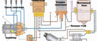
Connecting high-voltage wires ZMZ 405, ZMZ 406
ZMZ carburetor and Euro-2 engines are equipped with a DIS (Double Ignition System) ignition system.
The DIS system uses ignition coils with two high-voltage wires. Each coil operates a corresponding pair of cylinders.
The first coil works with 1 and 4 cylinders, the second coil works with 2 and 3 cylinders.
How to connect the ignition coils?
The ignition coil of cylinders 1 and 4 is located closer to the intake manifold, the coil of cylinders 2 and 3 is closer to the exhaust manifold.
Low-voltage coil wires must be connected to the coil in pairs. The pair of wires for coil 1-4 is slightly shorter than the pair of wires for coil 2-3.
Within the pair, it does not matter which contact is connected to which wire - the coils are non-polar. Also, within the pair, it does not matter which high-voltage wire goes to which cylinder.
Let's look at an example (see photo)
Coil 1 control (cylinders 1 and 4) – green and yellow wires. This pair connects strictly to the coil of cylinders 1 and 4!
Further:
Low voltage circuit - polarity is not important - can be connected:
Option 1: The top coil contact is yellow, the bottom contact is green.
Option 2: The top coil contact is green, the bottom contact is yellow.
High voltage outputs – polarity is not important – can be connected:
Option 1: Top outlet for cylinder 1, bottom outlet for cylinder 4.
Option 2: Top outlet for cylinder 4, bottom outlet for cylinder 1.
Coil 2 control (cylinders 2 and 3) – blue and yellow wires. This pair is connected strictly to the coil of cylinders 2 and 3! Further - similar to pair 1-4 - the polarity within the pair is not important.
The determining factor when connecting pairs of low-voltage and high-voltage wires to the corresponding ignition coil is the correctness of their routing. The wires should not be too tight, bent too much, and should not rub against fixed parts of the engine or other wires.
Another article about high-voltage wires ZMZ 405, 406 - read so as not to repeat this mistake.
Instructions for connecting short circuit
The ZMZ 405, 406 and 409 engines use two short circuits - one of them works with cylinders 1 and 4, and the second with cylinders 2 and 3. The first of them is located closer to the intake manifold, and the second is located next to the exhaust manifold. To make the connection correctly, low voltage wires should be connected in pairs - those used for the first coil (cylinders 1-4) will be shorter in length. Since the short circuits themselves are not polar, it does not matter which contact the cable will be connected to; it also does not play a role within the pair to which cylinder the wire will be connected (the author of the video is the SpawnyXC90 channel).
Spark plugs used on cars with ZMZ-405, 406 and 409 engines
Before you go to the store to buy spark plugs (SZ) for injector engines 405, 406 or 409, you need to read the service book for the car. The manual must clearly indicate the SZ models, the operation of which is allowed in such motors. The manufacturer officially recommends using SZ A14DVR or their analogues. If you decide to give preference to analogues, then keep in mind that the spark gap in the spark plugs should be 0.7-0.85 mm.
Some motorists, leaving reviews on the Internet, recommend using the SZ A17DVRM, but this is not allowed for two reasons:
- first of all, these products have a different heat dissipation parameter;
- In addition, their gap is 1 mm, and this is not suitable for these engines.
Finding A14DVR devices today is not so easy, so many car enthusiasts have to look for analogues.
So that you can choose a similar product, we suggest that you familiarize yourself with the decoding in more detail:
- A - this beech determines the diameter, as well as the pitch of the thread D. The original SZ uses an M14 * 1.25 thread.
- 14 is the value of the heat number. It is considered one of the main parameters that determine the characteristics of the temperature regime of the product.
- D is the value of the thread length. In our case, the SZ are equipped with a thread 19 mm long.
- B - determines how much the thermal cone of the insulator protrudes into the combustion chamber of the motor itself. Thanks to the protrusion of the cone, the product warms up faster when starting the power unit, and this, in turn, ensures its higher resistance to soot formation.
- The last symbol - P - determines the presence of a built-in resistor element in the SZ design. Thanks to the presence of a resistor, the level of interference for radio equipment, as well as the motor control module, is reduced. In general, the presence or absence of this element in the design of the SZ will not in any way affect the functionality and quality of spark formation when starting the internal combustion engine.
Replacement intervals and signs of malfunction
On average, the service life of modern SZ is about 20 thousand kilometers. Of course, this indicator depends on many conditions. First of all, this is the quality of the completed part, its operating conditions, as well as the quality of the fuel used. The last point is very important, since the use of low-quality fuel will lead to a significant reduction in the service life of the SZ.
What are the signs of faulty spark plugs?
- If you remove the SZ from its seat, you will see its body. The presence of soot and deposits on the device body, in particular on the electrode, may indicate a breakdown of the product. You can try to solve such a problem by cleaning, but this does not always help.
- Presence of oil traces on the SZ. Due to oil exposure, the product cannot work efficiently, so problems may occur in the operation of the SZ. Such devices need to be cleaned and dried, but before further use it is necessary to determine the reason for the contact of motor fluid with them.
- Also, fuel traces on the devices may indicate a malfunction of the SZ.
- Another sign is that the starter has to be turned for a long time, and the engine may start after a long period of time, or may not start at all. The same symptoms indicate a dead battery, a broken distributor, or an incorrectly functioning fuel pump.
- When the engine warms up, unpleasant and uncharacteristic sounds appear. They may also appear when idling.
- Fuel consumption during vehicle operation has increased significantly.
- In addition, the volume of harmful substances in exhaust gases has increased. Of course, this malfunction cannot be determined by eye; a more thorough diagnosis is required.
- The vehicle's traction has weakened significantly, its power has decreased, and the engine has difficulty picking up speed.
What does a candle affect?
Some car enthusiasts are sure that this is not the most important and by no means significant element in the car.
However, this is not at all true. It may seem this way because the spark plug simply converts voltage into a spark.
The quality of the spark that is created between the electrodes determines such indicators as quality, as well as the speed at which the working mixture burns. Needless to say, the power and fuel consumption of the car depend on this.
If the spark is insufficient, and this may be due to an incorrect gap between the two electrodes, then part of the fuel will fly out, as they say, into the pipe and will not do the work. It is also the fault of this part that happens. This happens due to damage to the insulating layer or loss of tightness.
Replacing spark plugs (including Gazelle 405) for any ZMZ engine will help solve the problem with a missing spark. However, different manufacturers produce models that are designed for specific operating conditions. On one engine, a set of new parts of the appropriate model may work well. But on another, the spark may be weak, which will affect the quality of fuel combustion.
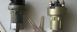
Features of the ignition coil device
The ignition coil (IC) is a small-sized transformer. A primary winding is wound on its magnetic core, and a secondary winding is installed on top of it, in sections. Both of them are installed in a plastic case, and the space between these components is filled with thermoactive polymer resin.
Also on the case there are low and high voltage contacts for connecting the device. In accordance with the coil connection diagram, low voltage pulses are supplied to the device from the control module. Once inside the device, these pulses are converted into high-voltage charges, which, in turn, are supplied to the SZ. The discharge is carried out simultaneously on two SZ (the author of the video is Alexander Terekhin).
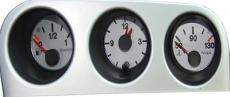
The microprocessor ignition system is designed to ignite the working mixture in the engine cylinders with setting the optimal ignition timing for a given engine operating mode
This system controls the operation of the forced idle economizer solenoid valve (IAS).
Using a microprocessor ignition system, more economical engine operation is achieved; By increasing its power indicators, engine operation with detonation is eliminated and exhaust gas toxicity standards are met.
This system is more durable and reliable compared to the classic ignition system.
There are no parts subject to wear (except for spark plug electrodes).
The MIKAS 7 control unit can be installed on some vehicles. 1.243.376-3-01.
— generation of electric current pulses for the operation of the electromagnetic valve EPH;
— ensuring the operation of the entire system in backup mode (in the event of failure of individual elements of the system);
— diagnosing system malfunctions.
The main element of the block - the microprocessor - makes all the calculations and generates all the necessary data that ensures the operation of the ignition system and EPH. The unit works complete with the following sensors and components:
— crankshaft position and speed sensor (synchronization sensor);
— absolute air pressure sensor in the engine intake pipe;
— engine temperature sensor;
- knock sensor;
— ignition coils;
— electromagnetic valve EPHH;
— diagnostic indicator lamp.
The microprocessor ignition system and EPHH operate as follows.
When the ignition is turned on, the warning light on the instrument panel lights up. At this time, the microprocessor operates in self-diagnosis mode.
After this mode ends, the indicator lamp goes out if no malfunction is detected, or lights up if a malfunction is detected.
If the indicator goes out, the system is operational and ready for operation.
When the engine is cranked by the starter, based on signals from the crankshaft position sensor, the control unit issues electric current pulses to the ignition coils to ensure the operation of the spark plugs in accordance with the operating order of the engine cylinders 1-3-4-2.
High voltage from each ignition coil is simultaneously supplied to two spark plugs:
- to the spark plug in the cylinder, where the compression stroke of the working mixture occurs (for example, cylinder 1) and the electric discharge that ignites it;
— at the same time, an electric discharge occurs in the second spark plug in the fourth cylinder, where the exhaust gas exhaust stroke occurs; this discharge does not affect the operation of the engine.
Malfunctions of the ignition system and EPH
The control unit has a self-diagnosis mode, which can be used to determine faults in the system.
If the control unit in self-diagnosis mode cannot determine the malfunction, then it is necessary to use a special device DST-2 with the appropriate cartridge (cassette with program).
In this case, you must follow the instructions supplied with the device.
In self-diagnosis mode, the control unit issues light codes to the warning lamp.
Each fault is assigned its own digital code. The digital code is determined by the number of times the warning lamp turns on.
First, count the number of times the lamp is turned on to determine the first digit of the code (for example, number 1 - one short turn on for 0.5 s, number 2 - two short turns on, then there is a pause of 1.5 s.
After it, the number of inclusions is counted to determine the second digit of the code, then the third, after which there is a pause of 4 s, which determines the end of the code).
If the code is three-digit, the first digit is displayed for 1 second.
To put the control unit into self-diagnosis mode:
— disconnect the battery for 10-15 s and connect again;
- start the engine and let it run for 30-60 s at idle speed, - connect the diagnostic socket terminals with a separate wire according to the figure.
The socket is installed in the engine compartment on the front panel on the left side. After the control unit is switched to self-diagnosis mode, the control lamp should display code 12 three times, which indicates the start of the self-diagnosis mode.
The following codes will indicate an existing fault or multiple faults. Each code is repeated three times.
After all the existing fault codes are displayed, code 12 is displayed three times and the codes are displayed again.
If the control unit cannot detect a malfunction or there are no malfunctions, code 12 is displayed. Diagnostic codes are shown in the table.
Code No. - Malfunction
12 - Self-diagnosis mode enabled
15 - Short circuit in the absolute air pressure sensor circuit
16 — Open circuit of the absolute air pressure sensor
21 - Short circuit in the engine temperature sensor circuit
22 — Open circuit in the engine temperature sensor circuit
25 - Low voltage level in the vehicle’s on-board network
51.52, 61-65 - Control unit malfunction
53 - Malfunction of the crankshaft position sensor or high level of interference in the vehicle’s on-board network
181 - Short circuit in the diagnostic lamp circuit (detected only by the DST-2 device)
182 - Open circuit of the diagnostic warning lamp (detected by the DST-2 device)
197 - Short circuit in the EPH valve circuit
198 — Open circuit of the EPHH valve
Engine crankshaft position sensor (timing)
An inductive sensor determines the angular position of the engine crankshaft, the synchronization of the control unit with the engine's operating process and its rotational speed.
Knock sensor
installed on the right side of the cylinder block in the area of the fourth cylinder.
Operating an engine with detonation can lead to destruction of engine parts (for example, piston, head gasket, etc.
The main elements of the sensor: quartz piezoelectric element 7 and inertial mass 6 (washer). When the engine is running, vibration of its parts occurs.
The inertial mass 6 of the sensor acts on the piezoelectric element 7; electrical signals of a certain size and shape arise in it.
The occurrence of detonation during engine operation sharply increases vibration, which increases the voltage amplitude of the sensor's electrical signals.
The electrical signals from the sensor are transmitted to the control unit.
Based on signals from the knock sensor, the control unit adjusts the ignition timing until detonation stops.
If the sensor or its electrical circuits fail, the control unit signals the driver by turning on the warning lamp.
The serviceability of the sensor can only be checked when the engine is running using the DST-2 device.
A faulty sensor should be replaced
temperature sensor
The coolant temperature sensor is a semiconductor element that changes its conductivity depending on the ambient temperature.
The sensor is installed in the thermostat pipe and is designed to determine the temperature of the engine coolant.
The sensor is included in the electronic circuit of the control unit, which, based on the voltage drop in the sensor circuit (depending on temperature), adjusts the ignition timing.
If a malfunction occurs in the sensor or in the sensor circuits, the control unit signals the driver by turning on the warning lamp.
The serviceability of the sensor must be checked using the DST-2 device; in its absence - by the magnitude of the voltage drop in the sensor circuit at different temperatures.
checked by the DST-2 device included in the vehicle.
Ignition coil
Ignition coils are designed to generate high voltage electric current to ignite the working mixture in the engine cylinders.
Ignition coils (2 pcs.) are installed on top of the engine.
The ignition coil is a transformer. The primary winding 5 is wound on the magnetic core 1, and the secondary winding 3 is wound on top of it in sections.
The windings are enclosed in a plastic housing 2.
The space between the windings is filled with compound 7.
The housing has low and high voltage terminals 6.
Low voltage electrical impulses are supplied to the ignition coil from the control unit.
In the ignition coil they are transformed into high voltage electrical impulses, which are transmitted through wires to the spark plugs.
An electrical discharge occurs simultaneously in two spark plugs of the first and fourth cylinders or the second and third cylinders.
For example, one electrical discharge occurs in the spark plug of the first cylinder when the compression stroke ends there; the second discharge occurs in the spark plug of the fourth cylinder when the exhaust stroke occurs there.
The electrical discharge in the spark plug of the fourth cylinder during the exhaust stroke does not affect engine operation.
With further rotation of the crankshaft, an electric discharge will occur in the fourth spark plug, causing high voltage current leakage and insulation breakdown.
If oil gets on the wires, they should be wiped with a rag soaked in gasoline.
If necessary, check the serviceability of the current-carrying wire with an ohmmeter. The resistance of the wires to the 1st and 2nd cylinders should be no more than 1000 Ohms, and the wires to the 3rd and 4th cylinders should be no more than 900 Ohms.
Spark plug tips
High voltage wires are connected to the spark plugs through special tips
The tip structure is shown in Figure 8
The resistance of a working tip should be no more than 8000 Ohms.
Technical differences
A power unit that has exhausted its service life is replaced, often giving preference to more modern versions.
Structurally, everything fits into the factory seats, and the differences, for example from the Gazelle Business, appear only in the electrical wiring diagram at the location of the equipment:
- Another form of connecting blocks;
- A different diagram for connecting devices;
- Different voltage.
Supply system
Leaving the carburetor in the past, replacing the power unit inevitably entails replacing the power system:
- A new gas tank is installed, since the injector must dump excess fuel back, and the old tank design is not suitable for this;
- The gas line is replaced (the return line is laid + the supply connection is modified);
- The operation of the injectors is regulated using connecting wiring.
Cooling system
The new injection engine ZMZ-406 is more demanding on the cooling system, therefore, during the installation of a new power unit:
- An electric fan is installed on the cooling radiator;
- The engine compartment wiring harness is being replaced.
Fuel injection control system
Do not forget that the power supply system of an injection engine is controlled by an electronic unit, which also needs to be connected to the vehicle’s standard electrical network. Accordingly, the electrical wiring on the Gazelle 406 is different than on older versions of the car with 402 series engines, and must be replaced.
injector for 402 engine
| Added: Sat Aug 05, 2006 12:58 am Post subject: injector for 402 engine | Reply with quote | |
| I have a gas 31029 with a ZMZ 402 engine, I want to try installing injection instead of a carburetor, I used injectors, sensors, a fuel pump from BMW as a basis, and the control unit is homemade, but with analog control of signals, has anyone tried anything like this? |
| to come back to the beginning | to come back to the beginning | to come back to the beginning | to come back to the beginning | to come back to the beginning | https://mpsz.ru/forum/about.php Interesting thing. Now I’ll have some money, I’ll definitely buy it (a complete set, i.e. with DD and on-board computer). |
| How did you determine the problem on pot 4? Lost compression? Those. there were bullies. Or something else? |
Before you start disassembling the engine
prepare all the tools, materials and accessories necessary for this. The set for work includes the following items: a mandrel for compressing rings; keys, collars, ratchets, heads and other representatives of the standard repair kit; torque wrench; head for unscrewing the front pulley KV. Traditionally, a 36mm head is suitable; mandrel for centering the clutch disc; set of hex keys; mandrel for arranging valve stem seals; valve desiccant; rags. For greater convenience and efficiency, try to get a bore gauge as well as a micrometer. Additionally, you will need a whole arsenal of various auto chemicals: sealants. ABRO products are highly respected among GAZ owners. To do this job you will need to prepare black and red or clear sealants; ceramic sealant. This product is used to treat the exhaust system; shellac varnish. For example, Done Deal products have proven themselves well; thread locker. An anaerobic type part is used. Recommendations regarding manufacturers of certain products are given in accordance with reviews from the majority of users. In general, you can focus on your preferences and, of course, your available budget, but if possible, try to use materials of the highest quality possible - this will make you much less likely to remember the need to repair the 406 engine of your GAZ.
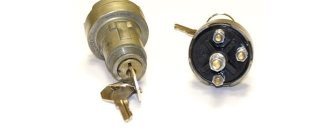
How to check short circuit?
How to check the short circuit yourself:
- First, disconnect the power cable from the negative terminal of the battery and turn off the ignition.
- Then open the hood and disconnect the two high-voltage cables from the product. Unscrew the bolts and also dismantle the bar along with the product. The second short circuit is dismantled in a similar way.
- The diagnostic procedure itself is carried out using an ohmmeter; its probes are connected instead of disconnected wires. After connecting the probes, it is necessary to measure the resistance level. If the product is operational and in good working order, then the resistance level should be about 0.4-0.5 Ohm.
- To obtain more accurate diagnostic data, you can also short-circuit the tester probes, and then perform resistance diagnostics again. In particular, you are now interested in the secondary winding of the device. If the device is operational, then the resulting value should be around 5-7 kOhm. If the diagnostics showed different values, this indicates that the short circuit needs to be replaced.
Photo gallery “Short circuit diagnostics”
Video “Instructions for setting the ignition”
Visual instructions on how to independently adjust the ignition in a Gazelle are given in the video below (author - GAZ 3110 Volga channel).
The topic of the article is very high-quality high-voltage wires ZMZ 406. I would especially like to emphasize that we are talking specifically about a 406 engine with one or two ignition coils, and not about a 409, where individual coils are installed on each spark plug. Of the total number of ZMZ 406 engines that I have encountered, I have encountered high-quality wires only a single time. And the reason was not because of the “green frog,” but simply because there was nowhere to buy them.
Checking high-voltage ignition wires without removing them from the car
This is a primitive but quite effective method. The simplest option is to install a known-good cable and compare the operation of the engine. If the location of the high-voltage wires allows, you can swap them (along with the connector on the distributor), and again read the errors with the scanner. It will indicate a different cylinder number.
Putting a dielectric glove on your hand, you can remove the tips from the spark plugs one by one while the engine is running. When you reach the problem cylinder, the nature of the work will not change.
Definition of breakdown “by eye”. In the dark you can see how the spark “sews” onto the body of the internal combustion engine. You can connect a thick wire to ground and run the bare end along the insulation. You will see the weak point immediately - a spark will strike.
Despite a whole bunch of breakdowns that armored wires can cause, their solution is no more difficult than replacing plugs in a home electrical panel. If a faulty one was identified, a new one was installed. If there is a problem, how to change high-voltage wires on the highway or in an open field (far from stores), remember that the cables do not break suddenly; regular diagnostics will help you not to be caught by surprise.
How to test candles?
During the visual inspection of parts, it is also recommended to check their performance. It is convenient and effective to control their operation using special stands that allow you to check sparking under different pressures.
If there is no such stand, you can unscrew the spark plug, then connect it to the tip of the high-voltage wire and touch the element connected to ground. Then the ignition starts. Here you need to let the starter crank the crankshaft several times. As a result, a strong spark of bright purple color should jump through. If it is weak and its color is faded, then this indicates a problem with the part itself and the spark plug may need to be replaced.
Typical unit malfunctions and ways to eliminate them
A malfunction in the operation of the short circuit can occur for the following reasons:
- There is a short circuit within the system, which may cause the device to overheat. If the operating temperature exceeds 150 degrees, the product will fail irrevocably.
- The second reason is a faulty power supply from the car's electrical network. As you know, for normal operation of electrical devices, the voltage level in the on-board network must be at least 11.5 volts. If the power is too low, it will take much longer to charge the short circuit.
- The device may also fail due to mechanical damage to the insulation. This problem is usually associated with engine fluid entering through worn out seals.
- Poor contact of the product with the on-board network. If the short circuit housing is damaged, this may cause moisture to enter the primary or secondary windings, which in turn can lead to the appearance of transition resistance.
- Thermal problems. Some short circuit models are more susceptible to heat generation than others, which can also affect their service life.
- As a result of exposure to engine vibrations, the performance of the short circuit may also be impaired.
When does a spark plug need to be replaced (“Gazelle Business”)
So, the malfunction is determined by the symptoms. So, if the power unit does not start well, and the starting process is difficult, then this is a signal about the need for replacement.
Another symptom that often occurs on units and UMZ-4216 is tripling. The car may jerk, and engine traction and power are significantly reduced. Significantly increased fuel consumption, exhaust gases with a high content of carbon dioxide, poor dynamics - all these are also signals for replacement.
If the owner pays attention to these symptoms in a timely manner, the problem can be solved by simply replacing the spark plug. If you do nothing, the result will be sad. Detonation may occur in the cylinders. It will be accompanied by a shock wave, which can provoke detonation of the charge remaining in the cylinder. As a result, the engine will greatly lose power, the crankshaft, as well as connecting rods and pistons will be severely damaged.
Small parts will simply burn out.
Checking the ZMZ 405 coolant temperature sensor
Checking the coolant temperature sensor 19.3828. If codes 21 (low coolant temperature sensor signal level) or 22 (high coolant temperature sensor signal level) appear during diagnostics, assemble the sensor test circuit shown in Fig. 1. Using resistor 1, set the current in the circuit to 1...1.5 mA. Voltmeter 4 should show a voltage of 2.96…3.02 V at a temperature of +25°C. At a temperature of +90°C, the voltage should be within 3.6…3.7 V.
Read more: How to change the heater on a Passat b3
Basic aspects of ignition installation
The main aspects to consider when installing the ignition by marks:
- First, you need to dismantle the front cylinder head cover; to do this, you need to unscrew four 12-point screws. In some engine modifications, dismantling also involves removing the fuel pump.
- Then the upper hydraulic tensioner located in the head is dismantled; to do this, two screws securing the cover are unscrewed.
- Next, the chain stabilizers are removed - the middle one, as well as the top one; for this, the two screws that secure them are unscrewed.
- After this, the camshaft sprockets are dismantled. The shafts themselves need to be fixed using a 27 key, while simultaneously unscrewing the screws that secure them. In modifications of engines 4063.10, the camshaft sprocket is removed along with the fuel pump drive eccentric.
- In accordance with the jig installed on the sprocket, six holes should be drilled in each of them. Their angular displacements should be 2, 30, 5, 00, 7 and 30 degrees from the set position of the factory hole, which is located along the axis of symmetry.
- If, when adjusting the phases, it is necessary to turn the camshaft clockwise, the sprocket itself should be mounted on one of the additional holes with a positive offset. It is located to the right of the standard hole.
Loading …
Engine Description
Previously, the engine was designed for newfangled power and ignition systems, which were controlled by a microprocessor.
This engine was the first to be equipped with four valves per cylinder, with hydraulic lifters and two camshafts with a double chain drive. An electronic fuel supply system and electronic ignition were also installed.
The four cylinders have an in-line arrangement, a water jacket and controlled fuel injection.
The ZMZ-406 injector runs on A-92 gasoline. Previously, a carburetor version of the 4061 engine was produced, which ran on seventy-sixth gasoline. It had limitations in terms of release.
The unit is unpretentious in maintenance. It has a high degree of reliability. Later, on its basis, ZMZ-405 and 409 units were developed, as well as a diesel version of the engine labeled ZMZ-514.
The disadvantages of the engine include the cumbersome nature of the gas distribution mechanism drive, which is explained by its low quality of workmanship and a number of technological shortcomings.