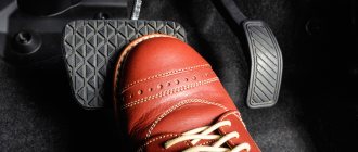
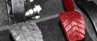
The parking brake (also known as the handbrake, or in common parlance “handbrake”) is an integral part of the car’s braking control. Unlike the main braking system used by the driver while driving, the parking brake system serves primarily to hold the vehicle in place when parked on sloped surfaces, and can also be used as an emergency emergency braking system in the event of failure of the main one. From the article we will learn about the design and principle of operation of the handbrake.
WHY DO YOU NEED A HAND BRAKE?
Before we talk about whether you need to use a manual mechanism or whether it is not necessary, you should understand why it is needed in general. Unfortunately, many novice drivers underestimate the importance of this mechanism until it comes to passing exams at the traffic police. The student gets into the car, puts on the seat belt, adjusts the seat and mirrors, depresses the clutch and engages first gear. And this could be the end of the whole exam. After all, the car, if it was not put on the handbrake, and at the same time is on an inclined surface, will certainly roll back. That's all, you will have to retake the exams.
But this is only the first and far from the last cruel joke that the handbrake mechanism can present. If there is no driver in the car, and the handbrake is not on, the car can arbitrarily go in the direction where the plane underneath it tilts. One can only guess about the consequences.
The handbrake functions as a wheel lock. Moreover, this action will continue until the car is removed from it. As you know, the main braking system of a car stops acting on the wheels as soon as your foot is removed from the brake. This effect of the handbrake on the rear wheels of the car is due to the peculiarities of the mechanism.
Parking brake device
mechanism that activates the brake (pedal or lever) The main elements of the handbrake include:
- cables, each of which acts on the main brake system, resulting in braking
The design of the handbrake brake drive uses from one to three cables. The three-cable scheme is the most popular. It includes two rear cables and one front cable. The first are connected to the brake mechanisms, the second - to the lever.
The cables are connected to the parking brake elements through adjustable ends. At the ends of the cables there are adjusting nuts that allow you to change the length of the drive. Removal from the brake or return of the mechanism to its original position occurs due to the return spring located on the front cable, equalizer or directly on the brake mechanism.
PRINCIPLE OF OPERATION OF THE HANDBRAKE
The mechanism of operation of the handbrake can be shown most clearly and easily using the example of a mechanically driven brake mechanism. Although today there are more complex and technologically advanced types.
Important! The manual parking brake is a system consisting of a control lever connected to the friction wheel disks through rods and cables.
When using the handbrake, pull the control lever towards you. The lever has a ratchet wheel that secures the lever in the working position. In this case, force is transmitted to the cables connecting the lever to the brake mechanism of the rear wheels. Three cable mechanisms are the most common, but they can have two or one cable. The system contains such a part as an equalizer. With its help, the central cable is connected to the side one. As a result, the force is distributed evenly to the right and left wheels.
The main brake elements and cables are connected using adjustable ends. Their use greatly simplifies maintenance and will allow, if necessary, to adjust units without replacing the main components. The hand brake can be easily tightened.
The cables are connected to the levers of the friction mechanisms. When transmitting force to the levers, they spread the brake pads and press them against the brake system drums. In order to unlock the wheels, it is enough to lower the handbrake lever, and the system will return to its original, non-working position.
HOW TO CHECK THE HANDBRAKE
Before you begin the rather labor-intensive work of tightening the handbrake, you need to check whether this is really necessary. You can diagnose the parking brake using a special stand in the service center. The easiest way to check the handbrake is to lift one of the rear wheels of the car, put the car on the handbrake and try to manually turn the wheel. If the wheel spins, it means that the parking brake is not working properly and most likely requires adjustment or replacement of the cable. There is another way to check the car’s handbrake, but it is more “cruel” in relation to the car’s brake pads and other elements of the braking system. The method is to put the car on the handbrake, then engage first gear and press the gas pedal to the floor. If the handbrake holds the car well, it will jerk slightly and immediately stall.
HOW TO TIGHTEN THE HANDBRAKE
The process of adjusting the handbrake usually does not differ much from car to car. There may be one key difference - adjustments are made under the car or from inside the car. The first option is more common, so it will be discussed in more detail. To pull the handbrake from under the car, you need to: Raise the handbrake 2-3 clicks (depending on the car model, this indicator may vary); Use a jack to raise the car. You can also use an inspection hole to make it more convenient to carry out work; Loosen the tightening nut on the adjusting unit.
Rotate the other nut to tighten the cable. Over time, you will notice that the braking force on the suspended wheel will become greater. When it cannot be turned by hand, this indicates that the cable is sufficiently tensioned; Next, lower the handbrake in the cabin to check whether, with it in this position, the wheel will turn without difficulty; If everything is fine, try raising the handbrake again; it is recommended to carry out such tests several times; Next, it remains to tighten the lock nut, and at this point the process of tightening the handbrake can be considered complete. As noted above, the handbrake can be adjusted from inside the car. The main difficulty in this case is getting to the necessary adjustment elements. Most often, to get to the adjusting nut, it is enough to remove the panel that covers the handbrake compartment.
Handbrake operation
You should always check the position of the handbrake before driving. Driving with a handbrake is not recommended; this can lead to increased wear and overheating of the brake pads and discs.
Is it possible to park the car with the handbrake in winter? This is also not recommended. In winter, mud and snow stick to the wheels and in severe frost, even a short stop can lead to freezing of the brake discs and pads. The movement of the car will become impossible, and the use of force can lead to serious damage.
We recommend: Which is better dependent and independent suspension, what are the differences
In cars with an automatic transmission, despite the “parking” mode, it is recommended to also use the handbrake. Firstly, this will extend the life of the “parking” mechanism. And secondly, it will save the driver from a sudden rollback of the car in a confined space, which, in turn, can lead to undesirable consequences in the form of a collision with a neighboring car.
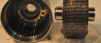
PRINCIPLE OF OPERATION OF HAND BRAKE ON DISC BRAKES
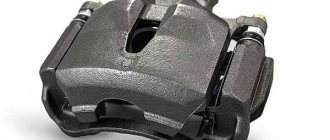
Disc brakes are installed on many vehicles due to the simplicity and reliability of the system. The operating principle of a handbrake on disc brakes is similar to that used on a bicycle. Depending on the car models, brake discs and the entire system as a whole may have a different design. But the most common type of design is a single-piston type, that is, a floating caliper. By compressing the rotor, it exerts a hydraulic effect. Here are the main components of a disc brake system:
- a caliper supplemented with a piston;
- pads;
- a rotor attached to the hub.
RECOMMENDATIONS FOR USING THE HANDBRAKE
You should not leave your car on the handbrake for more than two weeks, especially on the street. Humid air can cause corrosion and cause the pads to “stick” to the rims or drums.
It is necessary to check the serviceability of the handbrake at least once a month. The cables may become stretched and the handbrake will not work properly. If this happens, you will need to tighten the handbrake.
The general layout of an electric parking brake is shown in the figure.
Rice. General layout of the parking brake with electric drive: 1 – brake disc; 2 – brake pad; 3 – movable bracket; 4 – gearbox; 5 – electric motor; 6 – power supply; 7 – electric motor gear; 8 – electric motor; 9 – drive gear; 10 – swing gear; 11 – driven gear of the electric drive
The parking brake is turned on and off using a special switch. The brake is released by pressing the switch slide while simultaneously pressing the brake or accelerator pedal.
The parking brake can also be activated when the ignition is off by pulling the brake switch towards you. The car can be released from the brake only with the ignition on.
Operating principle of an electric parking brake
To perform the main function of the parking brake, it is necessary to convert the rotation of the electric motor shaft into a small forward movement of the brake piston. This is achieved by using a gearbox 4 with an oscillating gear in combination with a screw drive.
The drive features a three-stage speed reduction. The first stage is formed by a toothed belt transmission connecting the electric motor with the gearbox (with a gear ratio of 1:3). The second stage is using a gearbox with an oscillating gear (with a gear ratio of 1:50). Due to the use of a double gearbox, the speed of the gearbox output shaft is 150 times less than the speed of the electric motor shaft.
A swinging bevel gear 4, rigidly connected to it, is installed on the drive shaft of the gearbox. The axis of rotation of this gear intersects the axis of the drive shaft of the gearbox at an angle, therefore, when the drive shaft rotates, the gear makes a circular rocking motion. The swinging gear rotates on the hub of the drive gear and is equipped with two drivers 2 and 5, which fit into the guide grooves of the gearbox housing, which do not allow it to rotate relative to the gearbox housing, so it swings without rotating.
Rice. Reducer with oscillating gear: 1 – driven shaft; 2.5 – leash; 3 – drive drive gear; 4 – swing gear; 6 – driven gear
The oscillating gear has 51 teeth, and the driven gear has 50 teeth. Because of this so-called “pitch error,” the oscillating gear tooth is always pressed against the side of the driven gear tooth and never fits exactly into the gap between the teeth.
Rice. Meshing of the oscillating gear with the driven gear
When the drive shaft of the gearbox rotates, two teeth of the oscillating gear are constantly in mesh with two teeth of the driven gear. When the drive shaft is turned half a turn, another pair of teeth engages. In this position, the oscillating gear tooth engages with the driven gear tooth, interacting with its side surface. As a result, when the drive shaft is turned half a turn with each swing of the drive gear, the driven gear and with it the lead screw rotate through a very small angle corresponding to half the width of the tooth, which allows for smooth braking.
Rice. Operating principle of a gearbox with an oscillating gear: 1.5 – driven shaft; 2 – hub; 3 – hub tilt; 4.6 – meshing teeth of the swinging and driven gears
The transformation of rotational motion into translational motion is carried out by means of a lead screw 3 connected to the piston of the brake mechanism 5. The lead screw is driven directly from the gearbox with a swinging gear. Cylinder 6 is located in the cavity of the brake piston. Pressure nut 2 is pressed into the thickening of the cylinder head. The compression nut and the associated cylinder can slide freely along the brake piston without rotating relative to it. Rotation of the nut is impossible due to the special shape of the inner surface of the piston, which interacts with the figured surface of the pressure nut.
The speed of the motor shaft is determined using a Hall sensor. Thanks to this, the control unit can calculate the piston stroke.
When tightening the parking brake, the rotation of the lead screw 3 is converted into a translational movement of the pressure nut associated with the cylinder 6, which rests on the brake piston and presses the pads through it to the brake disc. In this case, the sealing ring of the piston 7 is deformed towards the pads. As the force of pressing the pads against the brake disc increases, the current consumption of the electric motor increases. The electromechanical parking brake control unit monitors the amount of current consumed during the entire process of tightening the brake and, when this current reaches a certain value, turns off the electric motors.
The screw thread is self-locking. Thanks to this, after the brake pads are brought together and the voltage supply to the electric motor is stopped, the brake remains tightened.
When the brake is released, the nut moves backward along the lead screw due to the counter rotation of the lead screw. The pressure on the cylinder stops. The piston moves away from the brake disc under the action of the elastic forces of the sealing ring 7, which tends to take its original position and the beating of the brake disc. In this case, the pads also move away from the brake disc.
Rice. Scheme of operation of the parking brake mechanism with electric drive: 1 – brake disc; 2 – pressure nut; 3 – lead screw; 4 – gearbox; 5 – brake piston; 6 – cylinder; 7 – sealing ring; a – tightening the brake; b – releasing the brake
The clearances in the parking brake drive are determined periodically when the vehicle is parked. They are adjusted automatically if, during the next 1000 km, the parking brake is not applied even once. To do this, the brake pads are moved from their original position until they touch the brake disc. The parking brake control unit determines the amount of pad travel based on the current consumed by the electric motor and compensates for pad wear.
We recommend: Window lifter button wiring diagram
The parking brake releases automatically when the driver closes the door, fastens the seat belt, starts the engine, and presses the accelerator pedal to move the vehicle. In this case, the moment when the brake is turned off depends on the pitch angle of the vehicle and the engine torque.
The use of an electrically driven parking brake allows for smooth starting and rolling back of the vehicle on a slope in the event of inept driver actions.
The following parameters influence when the parking brake is released:
- vehicle inclination angle, determined using a longitudinal acceleration sensor built into the parking brake control unit
- engine torque
- accelerator pedal position
- the degree of clutch disengagement, determined for vehicles with a manual transmission based on the signal from the clutch pedal position sensor
- desired direction of vehicle movement, determined by the position of the automatic transmission selector or by a signal received from the reversing light switch
In this case, the car cannot roll backwards, since the parking brake is released only if the torque transmitted to the wheels exceeds its calculated value corresponding to the angle of inclination of the road. If the engine torque exceeds the calculated value, the control unit turns on the electromechanical drives of both rear brake mechanisms.
The use of an electric parking brake allows you to avoid using it frequently, for example, when stopping at traffic lights.
If the service brake drive malfunctions, the vehicle can be braked using the Dynamic Brake Control system. The emergency braking function operates both with the ignition on and off. If you press and hold the electromechanical parking brake switch while the vehicle is moving, it will be braked at a deceleration of approximately 6 m/s2. At the same time, an audible signal sounds and the brake lights come on. At vehicle speeds above 7 km/h, the dynamic control system applies braking by increasing the brake fluid pressure in all four working cylinders. At the same time, the ABS/ESP system is activated, which ensures braking of the car without skidding. If the vehicle speed does not exceed 7 km/h, pressing and holding the parking brake switch button causes the vehicle to brake using the electromechanical brake actuators (similar to applying the parking brake in a parking lot). If it is necessary to interrupt the emergency braking when the vehicle is moving at a speed of more than 7 km/h, it is enough to release the parking brake switch button or press the accelerator pedal.
Purpose and types of handbrake
The parking brake system is present on vehicles of all categories - cars, trucks and medium-duty commercial vehicles. The hand brake is used for the following purposes:
- securing the vehicle in place during long-term parking;
- braking a car with a running engine at stops when the driver needs to leave the cabin for a short time;
- keeping the car from rolling on sections of the road that have a slope;
- moving uphill;
- in some cases - to ensure an emergency stop of the vehicle.
Reference. Modern cars equipped with automatic transmissions use a safety algorithm for forgetful drivers. After turning the automatic transmission selector into Drive mode, the car will not move until you release the handbrake.
Depending on the category, brand and configuration, the following types of handbrake are installed on the vehicle:
- the most common is mechanical (cable);
- hydraulic;
- electromechanical (in everyday life it is often called electronic);
- pneumatic.
For drivers of passenger cars, cable and electromechanical drives are of greatest interest. Hydraulic ones are less common, and only multi-ton trucks are equipped with pneumatics.
Parking brake device: classic design
The classic of the parking brake genre is, of course, the mechanical design. It is familiar to owners of creations from the domestic automobile industry and foreign cars, so let’s look at its structure in more detail. It consists of the following parts:
- a hand lever or, less commonly, a foot pedal;
- cable system;
- rear wheel brakes.
The principle of operation of the system is quite simple. The lever, which in our case will be the usual manual one, is equipped with a ratcheting mechanism that reliably locks it in the raised or lowered position. When we lift it, the force on the brake mechanisms of the rear wheels (only they are connected to the handbrake) is transmitted through metal drive cables, of which there can be from one to three (usually three - the central one and two rear ones, connected through an equalizer, ensuring uniform distribution of forces on both mechanisms).
When stretched, the cables press the brake pads against the discs or drums - the car will not move anywhere. When we lower the lever, the tension of the cables weakens, the pads release the discs or drums and we can go.
Most easily from the point of view of engineering refinements, the above-mentioned scheme is implemented on drum brakes, which is why they have long remained and remain indispensable on the rear wheels of budget cars. All you need to do is equip the drum with an additional lever that transmits force from the handbrake cable.
Things are a little more complicated with disc brakes. The engineers had to work a little with them, and as a result, three options for connecting them to the handbrake appeared:
- screw mechanism;
- cam;
- drum
The first two types are typical for single-piston calipers. Their device is similar. In a screw circuit, the cable is connected through a special lever to a screw screwed into the disc caliper piston. When tensioned, the screw rotates and causes the piston to move, which presses the pad against the disc.
In the cam version, the piston is acted upon by a system of a cam and a pusher, which is connected to a cable through a lever. The drum variety is used in multi-piston disc brakes. Essentially, this is a separate drum-type brake mechanism, mounted on a disc and not connected to the main calipers and pads.
How many brake systems are there in a car?
Three. And all of them provide the functions of changing the speed of the vehicle, stopping and holding in place, using the frictional force and reaction of the support between the wheel and the road surface material. So, the types of braking systems:
Working - provides a controlled reduction in vehicle speed, if necessary, even to a stop. Consists of a drive for transmitting force and a braking mechanism. It is usually of the friction type, installed in the wheel and divided into two types, drum and disc. The drive and force transmission system is also divided into several types:
- Mechanical drive
- Hydraulic
- Electric
- Pneumatic
The first three types of drives will be discussed in detail in further material of the article.
Spare - performs the functions of a working one in case of its complete or partial failure. Structurally, it can be a standalone unit or be part of the main system. Uses working system mechanisms.
How it Works The way a parking brake works is most easily explained using a mechanically operated system as an example. A mechanical hand brake is a system of a control lever, connected through rods and a system of cables to the friction mechanisms of the wheels .
The handbrake lever, equipped with a ratchet wheel for locking in the working position, transmits force to a system of one, two or three cables connected to the brake mechanism of the rear wheels of the vehicle. The most popular scheme is using three cables, one central and two lateral. To ensure equal force on the brake mechanisms of the right and left wheels, the central cable is connected to the side ones through a special part of a complex shape, the so-called equalizer.
The parking brake elements are connected to the cables via adjustable ends. This scheme allows you to adjust the system without labor-intensive replacement of the main drive elements.
The levers of the friction mechanisms connected to the cables spread the brake pads, pressing them against the surface of the drum. You can unlock the parking brake, or remove the car from the handbrake, by lowering the mechanical drive lever. The return device will return the pads to their original position and release the brake drum.
Watching a short video will help you understand more clearly how the parking brake works.
Historical reference. Drum brakes were invented by French engineer Louis Renault in 1902. Until the 1930s, a scheme was used in which the pads were moved apart using a system of levers; later, small brake cylinders began to be used. The drum brake design means the pads wear out quickly, and until the invention of the self-adjusting mechanism in the 1950s, the system required constant adjustment. Since 1970, disc brakes have been installed on the front wheels of passenger cars. On the rear ones - as a rule, drum ones, since the parking brake works most effectively with this type of friction mechanisms.
How does the electric handbrake work?
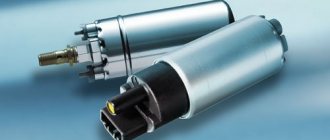
This system consists primarily of a braking mechanism. It includes the stock brakes with minor upgrades to the cylinder design. Since electronics are involved in the work, it is logical that it will not be possible to do without input sensors. These include a button that turns on the system. It can be installed either next to the gearbox lever or on the main console (it all depends on the make and year of manufacture of the car). The system also contains a slope sensor (most often mounted in the ECU) and a clutch sensor (installed on the clutch drive and transmits data on the release speed and the exact location of the clutch pedal).
The ECU receives the necessary information from the sensors and converts it into a signal that is sent to the actuators. The brake actuator comes into play (activates the pads), which consists of:
- Electric motor. It transmits rotational impulse.
- Belt drive (receives rotational impulse and transmits it to the gearbox).
- Planetary gearbox (allows you to reduce the weight of the drive and partially suppresses noise). This element moves the screw drive.
- Screw drive. Thanks to it, translational movements of the brake elements are carried out.
Healthy! The electric handbrake is combined with the car control system and the unit responsible for directional stability (ESP).
Thanks to this system, the car owner does not need to pull or release the cumbersome parking brake lever every time (which many people sometimes forget about). Therefore, EPB makes life much easier for motorists.
How the handbrake works
The mechanism is activated by moving the lever to a vertical position until the latch clicks. As a result, the cables that press the brake pads of the rear wheels to the drums are stretched. The rear wheels are blocked and braking occurs.
We recommend: Design, principle of operation and types of DSG gearbox
To remove the car from the handbrake, you need to hold down the locking button and lower the lever down to its original position.
Parking brake in disc brake mechanism
As for cars with disc brakes, the following types of parking brakes are used:
- screw;
- cam;
- drum
Screw type is used in disc brakes with one piston. The latter is controlled by a screw screwed into it. The screw rotates due to a lever connected on the other side to a cable. The piston slides in along the thread and presses the brake pads to the disc.
In a cam mechanism, the piston is moved by a pusher driven by a cam. The latter is rigidly connected to the lever using a cable. The movement of the pusher with the piston occurs when the cam turns.
The drum brake mechanism is used in disc brakes with multiple pistons.
Features of operation
When operating a vehicle with a mechanical brake, it is recommended to observe the following rules:
- lower the handbrake before starting to move, otherwise the wear of the brake pads and discs will accelerate;
- do not put the car on the “handbrake” in winter, as at this time of year the pads may freeze to the discs;
- Always raise the handbrake in cars with automatic transmission and the “Parking” function, as this will prevent the car from rolling back.
On vehicles with EPB, the condition of the electromechanical parking brake must be checked regularly. The mechanism must not be left running for an extended period of time. Because of this, the battery quickly discharges, as a result of which it becomes impossible to move away. In addition, when carrying out repair work on the car, the EPB electronics must be switched to service mode. This will help avoid additional breakdowns. Author: Fedor Averyev
Electromechanical parking brake
The development of electronic computing systems and the active use of on-board computers in the automotive industry has led to the replacement of many mechanical elements with program-controlled units. This innovation did not bypass the braking system. The electric, or as it is also called, electronic parking brake is an autonomous unit operating under the control of the vehicle’s on-board computer.
Structurally, this device consists of an electric motor, a belt drive, a planetary gearbox and a screw drive. The electric parking brake is installed on the rear wheel caliper of the vehicle.
When a control signal is supplied, the electric motor communicates rotational motion to the planetary gearbox via a belt drive. The latter, by reducing the speed of the electric motor, acts on the screw mechanism responsible for pressing the pads to the brake disc.
Electronic parking brake drive. Diagram of the executive part.
The electromechanical parking brake includes:
- input sensors;
- electronic control unit.
The slope sensor informs the on-board computer about the position of the car relative to the horizon, the clutch sensor records the position of the pedal and the speed at which it is released.
When you press the power button located on the front panel of the car, the electric drive of the parking brake, acting on the clamping screw, attracts the pads to the brake disc. The electric parking brake is released automatically when you press the accelerator pedal. There is also a “manual” removal mode - when you press the brake pedal.
When the brake is released, the electronic control unit analyzes the vehicle's lean angle, the position of the accelerator pedal and the clutch release speed. This data helps you choose the right time to release the brake discs, which creates an exceptionally comfortable driving experience.
Scheme of connecting an electromechanical braking system to the on-board control network of a modern car.
You should not leave your car with the parking brake on for long periods of time, more than two weeks. In humid air, brake pads can “stick” to the discs or drum, completely immobilizing the car. The same situation can happen in the cold season. Moisture deposited on the brake mechanisms can interfere with the normal operation of the system.
You should check the operation of the handbrake at least once a month. This is especially true for vehicles with a mechanically operated parking brake. Cables transmitting force can stretch, which will lead to extremely unpleasant consequences.
The problem of parking heavy vehicles on road slopes has been known for a long time. A car with a manual transmission can be easily moved when parked with the engine off. To solve this problem, a parking brake was invented, which is now widely used not only in cars, but also in trucks.
The main braking system in a car has a pedal, which is used to control the brakes. Using the pedal, you can gently reduce speed or use emergency braking to prevent a collision. But using the main braking system without the participation of the driver is impossible, therefore, during long stops, a handbrake is used, which has cables that block the wheels.
Hydraulic system tuning
Hydraulic drive is used in most modern machines. A simple and reliable device, a minimum of complex and fragile parts, allow it to remain in service even in the age of electronic computing and control units that have replaced many mechanical elements in the design of a car. A simple diagram includes:
- master brake cylinder;
- expansion tank;
- pressure regulator;
- two brake circuits, for the front and rear wheels of vehicles.
When you press the pedal, pressure is created in the system, which is transmitted to the brake cylinders located in the wheels, which press the pads against the surface of the discs or drums. Unlocking when pressure is removed is performed using a return mechanism.
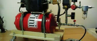
The operation of the hydraulic handbrake will become clearer after watching the next video. Many car enthusiasts, dissatisfied with the way the mechanical parking brake drive works, decide to modify the main brake system. The hydraulic hand brake is installed on the circuit that serves the rear wheel mechanisms. All elements of the mechanical drive are mercilessly removed.
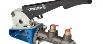
In appearance, the handbrake used for modification is practically no different from its mechanical “brother”. The same handle with an unlock button, the same ratchet mechanism, but instead of a central cable there is a hydraulic cylinder, not much different from the GTZ of the main system.
External view of a hydraulic hand brake.
Now the pressure in the brake circuit responsible for the rear wheels of the car can be created not only together with the front circuit, as happens during normal operation of the main system, but also by tightening the handle of the hand parking brake.
Diagram of installing a hand brake in the hydraulic system of a VAZ car.
The main advantage of this type of modification is ease of maintenance. The hydraulic drive of the parking brake operates without a force equalizer on the right and left wheels. According to Pascal's law, which describes the behavior of fluid in communicating vessels, the pressure at all points of the brake circuit will be the same.
The main disadvantage is a decrease in the reliability of the system as a whole. The mechanical parking brake drive operated independently of the hydraulic service brake system. Now, a breakdown of the circuit and loss of fluid threatens to leave the car without an emergency stop.
Cable drive design
The handbrake device of this type, installed on the vast majority of passenger cars, is simple and provides for autonomous activation, independent of the main system. How standard service brakes function:
- The driver pressing the pedal in the cabin sets the piston of the main hydraulic cylinder in motion.
- Under the influence of the piston, pressure is created in tubes with incompressible fluid laid to all wheels.
- Transmitted to the working cylinder of the wheel, fluid pressure pushes the pistons of the drum or disc brake. In the first case, the pads are moved apart and the force of friction stops the rotation of the drum. In the second, they tightly compress the spinning disk.
For parking braking, the handbrake uses standard elements - pads, but moves them apart with its own mechanical drive, consisting of the following parts:
- the above-mentioned lever in the cabin, equipped with a locking mechanism in different positions and a push-button unlocking device;
- the main cable connected to the lever and ending with a mounting bracket or an arcuate guide;
- secondary cables connected to the main one and connected to the brake levers of the rear wheels;
- cable adjustment mechanisms (spacers, nuts and springs), suspension brackets to the underbody;
- spacers between the pads.
Note. The main cable is connected to the rear drum mechanisms in two ways: with one cable hooked in the middle to a guide, or with two separate drives.
The rod system is usually hidden under the bottom in the recess of the central tunnel. Cable drives are equipped with protective covers that prevent corrosion. How does a mechanical handbrake work:
- The driver lifts a handle in the cabin, which automatically locks into the selected position.
- The traction moves the main cable forward, and it carries the secondary drives along with it through a mounting bracket.
- A lever inside the drum mechanism rotates and pushes the upper ends of the shoes apart. The automatic regulation function is taken over by the spacer bar.
- When the driver removes the car from the handbrake, the springs inside the drums tilt the lever back and the pads move. At the same time, the spring pulls the cable drive back to its original position.
The parking brake described above locks the drum wheels mounted on the rear axle. On cars equipped with brake discs, the same principle works: a cable pulls a lever, which causes the pads to compress. The only difference is the location and shape of the lever - on disc brakes it is placed outside, behind the hub.
How is a handbrake useful?
In fact, this type of brake does not always work with a handbrake. Depending on the origin and type of car, it can be activated by tightening the lever with your hand, pressing your foot, or a special button, which is why in the technical literature it is tolerantly called parking.
In addition to its main function - immobilizing the car during a long stop, it can be used as an emergency system in case of failure of the main brake. But this is not all the purpose of the hero of today’s article.
How else can it be useful? For example, the handbrake is indispensable when starting up a hill, and is also loved by enthusiasts of aggressive and extreme driving.
Application situations [edit | edit code]
- Starting on a steep hill;
- Parking on site;
- Brief exit from the car (gas station, store, etc.)
- Prolonged use of the main brake (parking in a traffic jam, in front of a traffic light, etc.);
- Failure of the main brake system. In the event of an emergency, you need to brake by sharply and strongly pulling the brake handle, avoiding prolonged friction of the brake pads on the drum, since in this case the friction linings and mechanism overheat and the maximum braking torque decreases;
- To enter a controlled drift.
Long-term storage of a car with the parking brake is not recommended, as the pads may stick (and freeze in the cold season) to the drum.
Instructors at driving schools teach how to skid park by engaging first gear, turning the steering wheel and pulling the handbrake (this technique is mainly used in emergency preparation).
“>
We recommend watching:
- Internal size of the brake drum VAZ 2107
- VAZ drum brake pads
- How to disassemble drum brakes
Wheel rim landing parameters- How to pull the handbrake on the West
Installing disc brakes instead of drum brakes
Things to remember
Although EPB can regulate itself, it will have to undergo periodic inspections. In this case, the car is installed on a stand and, using special diagnostic equipment, the mechanic checks the proper operation of the system.
If it's time to change the brake pads, you need to act very carefully. During any technical work, the electromechanical part must be in service mode. If you miss this point, there is a high risk that the electric handbrake will activate on its own during the work process and damage the vehicle or the mechanic himself.