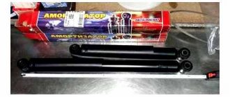
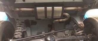
Repairs to the chassis and suspension probably have to be done most often on the Niva. Firstly, these are the most vulnerable parts on the Niva, and on any other car, and secondly, all this wears out very quickly due to the fact that such cars are operated in conditions that are far from ideal. Replacement of reaction rods, longitudinal rods, rear and front shock absorbers, ball joints and many other parts that need regular replacement. All these procedures are described here using the example of an old Niva, which was dismantled.
Construction and repair of the VAZ 2121 Niva car
Our additional
services and sites:
S Aratov
Statistics
| e-mail: | [email protected] [email protected] |
| icq: | 613603564 |
| skype: | matrixplus2012 |
| telephone | +79173107414 +79173107418 |
Chassis, front suspension, device
The front suspension is independent, pinless with anti-roll bar. The type and design of the suspension ensures a smooth ride and stability of the vehicle at high speeds.
The connecting link of the front suspension is the cross member 43 (Fig. 123) of tubular cross-section. Brackets 49 are welded on both ends of the cross member, with which it is attached to the body side members. The brackets have bosses with holes into which bushings 48 of the axles 44 of the lower arms 46 are pressed. Two .37 brackets are welded to the rear of the cross member pipe for fastening the braces 20. The other end of the brace is attached to the bracket 21 of the body. The braces absorb longitudinal forces and their moments while the car is moving and thereby protect the cross member mounting bolts from shearing.
The lower suspension arm is welded from two parts, which at the junction form a socket for attaching the lower ball joint 60. The arm 46 is connected to the suspension cross member 43 by an axis 44 through rubber-metal hinges. The rubber bushing 39 of the hinge is installed with a large radial interference between the outer 40 and inner 41 bushings. The outer bushing of the hinge is pressed into the hole of the lever 46. The axis 44 of the lower lever passes through the inner bushing 41. At the end of the axle, the rubber-metal hinge is clamped between thrust washers 42 and 38 with a nut. When the suspension arm swings, elastic deformation of the rubber bushing occurs without its rotation relative to the hinge parts. Thrust washers 38 and a set of technological washers 47 with a thickness of 0.5 mm are installed between the end surfaces of the rubber-metal hinges and the bushings of the cross member axis. By changing the thickness of the set of washers, the longitudinal inclination of the turning axis is adjusted. The lower support cup 50 of the suspension spring is attached to the top of the lower suspension arm.
The upper suspension arm 28 on the outer forked part has a seat for attaching the upper ball pin 23. Rubber-metal hinges of a similar design to the hinges of the lower arms, but of a different size, are pressed into the eyelets of the lever. On the lever 28 there is a platform for resting on the rebound buffer 30. The upper arm assembly with rubber-metal hinges and a forged steel axle 31 is attached to the side bracket 49 of the suspension. Between the axle and the cross member bracket there are spacer washers and adjusting washers 32, by changing the number of which the camber and longitudinal inclination angles of the front wheels turn axis are adjusted.
The suspension arms are connected to the steering knuckle 11 using ball joints. Each hinge is attached to the lever with three bolts. The hinges are non-separable, the upper and lower ones are of the same design, interchangeable, and do not require lubrication during operation.
The steel ball pin 13 with its spherical head rests on a bearing 15, the base of which is resin, poured into the body 17 of the ball joint, and the friction surface is Teflon fabric, which tightly fits the spherical surface of the pin. The hinge parts are protected from contamination by a rubber reinforced cover 14. The conical part of the pin 13 is installed in the conical hole of the steering knuckle and secured with a self-locking nut.
The design of the suspension and its elastic elements ensures a smooth increase in the rigidity of the suspension during its dynamic movements, and also increases its energy intensity. The elastic elements include spring 51 and rubber buffers 30 and 53 for rebound and compression. The rebound buffer 30 is held by a mushroom-shaped shank in a bracket 29 attached to the suspension cross member and body side members, as well as to the upper suspension spring support. The compression buffer 53 is held by a shank in a cage connected by contact welding to a post welded to the upper support.
Which silent block is better for Niva?
Changing the silent blocks of the front levers on a Chevrolet Niva
When disassembling the front suspension of a VAZ 2121 and its modifications, many car enthusiasts are faced with the question of how to remove the bolt of the Niva lower lever. The fact is that this bolt is the axis on which the lever rests and turns. Therefore, when repairing the chassis, this unit cannot be bypassed; the bolt still has to be removed. Sometimes solving a problem can be quite complex and time-consuming, which is something that motorists who service their Niva themselves would do well to know.
The silent blocks of the front suspension of a VAZ 2121 or Chevrolet Niva are able to withstand any abuse over a period of 80-100 thousand kilometers. If the operation is mainly asphalt, even more. Today we will replace the silent blocks of the upper arm on the Niva (2121, 21214, 21213, 2123) and choose the best one in terms of quality.
To replace the silent blocks of the upper arm we will need:
- 22mm socket wrench.
- Hammer.
- Penetrating lubricant WD-40.
- Puller for silent blocks or hydraulic press.
- A set of new upper arm silent blocks.
Puller for silent blocks
Perhaps, in difficult cases, a gas burner will come in handy. If there is one, you don’t have to think too much about how to press the silent block out of the lever, but simply burn out the rubber and knock out the remains of the silent block from the seats. If you have all this, you can start working.
- We park the car on a level surface, tighten the handbrake and jack up the front end.
- We install a stand under the lower arm, lower the car onto the stand to unload the upper arm. This is a must!
- We remove the wheel and clean the nuts securing the silent blocks from dirt, and also clean and lubricate the nuts securing the upper arm axle with penetrating grease.
- We unscrew the three nuts securing the upper ball joint and at the same time check the condition of its boot. Raise the lever on the axle.
- Without forgetting about the adjusting washers and without losing them, we remove the entire lever assembly.
- Using a 22 wrench, unscrew the nuts securing the silent blocks and thrust washers.
- We tighten all the nuts only after the suspension is loaded, that is, with the car lowered onto a stand under the lower control arm. After replacing the silent blocks, it is advisable to check the camber/toe of the front wheels.
Key Features
The front suspension of the VAZ 2121 is independent, on steel wishbones, with coil springs, double-acting telescopic hydraulic shock absorbers and a stabilizer bar.
The upper and lower arms of the VAZ 2131 have a similar design: at the ends of the “fork” there are cylindrical eyes for rubber-metal hinges (silent blocks), and on the opposite side there is a platform with three holes for attaching a ball joint. On the front branch of the upper arm there is a boss into which the rebound buffer rests at maximum suspension travel, and on the lower arm there are four holes for attaching the lower spring support cup.
The ball joints of the upper and lower arms are interchangeable and unified with the upper ball joints of the suspension of rear-wheel drive VAZs. The support is attached to the lever along with the boot and the pressure plate with three bolts with spring washers and nuts. The threaded ends of the pins of both the upper and lower bearings point downwards and fit into the tapered holes of the steering knuckle. The pins are secured with self-locking nuts. Thus, the steering knuckle can rotate about an axis passing through the centers of the ball joint pins.
The suspension arms, in turn, can rotate on their axes within the range of the rubber-metal hinges of the VAZ 2131 (limited by their elasticity). The upper arm axle has two holes and threads on both ends. Bolts pass through the holes, securing the axle to the suspension cross member. There are washers installed on the bolts between the axle and the cross member to adjust the camber angles and the longitudinal inclination of the wheel axis (see below).
The threaded ends of the axle fit into the rubber-metal hinges of the lever. There are washers on both sides of each hinge: the smaller one (flat) is on the inside, the larger one (convex outward) is on the outside. The self-locking nuts of the upper arm axle are finally tightened only when the suspension is compressed (on a loaded vehicle), otherwise the hinge will not be installed correctly and will quickly fail.
The lower arm axle is a bolt that passes through a bushing in the suspension cross member and the rubber-to-metal joints of the arm. Just like the upper ones, the lower hinges are tightened between two washers, but another thrust washer (thick) adjacent to the bushing, and several adjusting ones (thin) are added between the inner washer and the bushing. The thickness of the washers package is selected at the factory; when dismantling the suspension, you must remember their number and location. Changing the number and location of washers is permissible only if it is necessary to restore the suspension geometry of the VAZ 2121, Niva 2131 (for example, after an accident, replacing a cross member, etc.).
In this case, the distance between the outer washer and the flange of the bushing of the rubber-metal hinge after tightening its nut should be in the range of 3–7.5 mm. In the event that it is impossible to adjust the longitudinal inclination of the steering axis (see below) with working suspension parts, you can move some of the washers from one end of the lever to the other.
When to change the upper arm silent blocks
The service life of the upper silent blocks of the front suspension on the Niva is quite high. However, signs of wear may appear already after a mileage of 70-80 thousand km, or even earlier if the car is operated on a dirt road. The first sign of a worn silent block is a creaking and knocking sound when driving over uneven surfaces.
In the most advanced cases, a worn silent block will affect the car's handling and ability to keep a straight line; increased uneven tire wear and yaw along the road in a straight line are possible. The easiest way to determine the condition of the silent block is visually - there should be no cracks or chips on the surface of the rubber, and there should be no delamination or play.
Which silent block is better for Niva?
There are two dozen different silent blocks on sale, ranging from factory VAZ ones to polyurethane ones of various hardnesses. It is not advisable to install polyurethane silent blocks that are too hard - all the vibration will be on the body, and in cold weather a squeak is guaranteed.
- BRT, Balakovo, article 2121-2904040 and 21210-2904040, price about $9;
SEVI, Kedr, BZAK (Belebey) at about the same price and about the same quality, the price per set is about 12 dollars;
The quality and characteristics of polyurethane silent blocks strongly depend on the rigidity of the material, so they must be installed with the expectation that vibrations on the steering wheel and body will be inevitable, and the service life is unpredictable. According to the owners' reviews, the best option for the Niva is VAZ rubber silent blocks, which have proven themselves well over many years of operation.
There are two dozen different silent blocks on sale, ranging from factory VAZ ones to polyurethane ones of various hardnesses. It is not advisable to install polyurethane silent blocks that are too hard - all the vibration will be on the body, and in cold weather a squeak is guaranteed.
Purpose and design of the product
The main purpose of a silent block or, in simple words, a rubber-metal hinge is to connect suspension parts and dampen oscillatory movements due to the rubber filling inside the product. A truly useful product that has the simplest design. It is a silent block, a metal double bushing with rubber or polyurethane filling inside. This filling plays the main role of damping vibrations and vibrations. The photo below shows silent blocks.
These parts are installed mainly in the front suspension of the Niva Chevrolet vehicle. With their help, the connection between the front suspension arms and the anti-roll bar is ensured. A similar connection is provided in the vehicle's rear suspension, gearbox and engine.
Location of the upper silent block
Video process of installing silent blocks
Tools:
- Straight box spanner 22 mm
- Puller for removing and installing silent blocks
- Chisel
- Small hammer
Parts and consumables:
- Upper arm silent block (4 pcs.)
Replace silent blocks when they are worn or damaged.
1. Remove the upper arm assembly with silent blocks and axle from the vehicle as described here.
2. Using a 22mm wrench, unscrew the two axle nuts.
3. Remove the thrust washer.
4. To press out the silent blocks, install a puller on the lever so that its cup rests on the end of the lever eye, and screw the puller bolt with an internal thread onto the axle.
5. Tighten the nut of the puller bolt (while holding the bolt from turning).
6. Press the silent block out of the lever.
7. Having removed the silent block from the axle, install it in the eyelets of the lever and use a puller to press out the second silent block.
8. If there is no puller, pry the outer bushing of the silent block with a chisel.
9. Press it out.
10. To install new silent blocks, use a cup puller to press one silent block into the eye of the lever.
11. Before pressing in the second silent block, clamp the lever in a vice, insert the axle with thrust washers into the eyelets of the lever and screw the nut onto the axle from the side of the pressed silent block. We insert the second silent block into the eyelet.
12. Insert a mandrel made from a suitable piece of thick-walled pipe (length 160 mm, internal diameter 42 mm, slot width 32 mm) between the lever eyes.
13. We rest the puller cup against the end of the outer bushing of the silent block.
14. Screw the puller bolt onto the lever axis and press the silent block into place.
Some pullers for removing and installing silent blocks have a half-cylinder that helps tighten the second silent block of the upper arm. The half-cylinder rests on a bolt that is inserted into the axle. Then the pipe section is not needed, skip steps 12,13,14.
15. If there is no puller, we rest the end of the lever eye on the jaws of the vice. We press in the silent block with a tool head of a suitable size (a piece of pipe).
16. Install the lever in the reverse order.
The upper arm axle nuts are finally tightened in the “car on wheels” position. After replacing the silent blocks, check and, if necessary, adjust the wheel alignment angles. Use the services of workshops with special equipment.
The article is missing:
- Photo of the instrument
- Photos of parts and consumables
- High-quality photos of repairs
Rubber-metal hinges of the front suspension have a service life of no more than 80-100 thousand km. Depending on operating conditions, the lifespan before replacing silent blocks on Niva 2121 and Urban is reduced significantly. Diagnosis should be made for the following symptoms:
- Loss of straightness of movement, the car “moving” to the side at a constant speed or braking; Spontaneous changes in wheel alignment angles, uneven tire wear; The presence of booming sounds, rattling when working out irregularities; Body rocking VAZ 21214; The appearance of cracks, scuffs, and tears in rubber and metal structural elements.
Lack of timely attention to the problem leads to damage to adjacent suspension parts, deterioration of controllability and driving safety.
Unscrew the wheel bolts, remove the wheel, having first installed a reliable support.
This is what a spare part looks like, not suitable for further use.
Loosen the bolted connection of the upper ball joint (3 pcs), and then move the part up. Attention, an insufficiently unloaded element can cause injury.
Remove the upper arm assembly using 2 19mm wrenches. If soured, use WD-40.
Place the element in a vice, unscrew the 22 mm nuts from the ends, and remove the thrust washer.
Armed with a puller, press out the silent block.
In the absence of a specialized device, it is permissible to use a chisel. In this case, use a hammer to pry up the edges and remove the hinges.
To install a new part, a puller and a spacer or a tool head are required. When you first set up tools, secure one of the silent blocks in the eyelet.
Secure the lever, insert the complete axle, and secure the installed rubber-metal hinge with a nut. Install the remaining silent block in its place, as well as a 160 mm piece of tube (mandrel) between them.
Place the puller cup against the free end.
Tighten the nuts until the elements are completely installed in their original position.
In the second case, placing the eye on the support, hammer the silent block with a pipe of a suitable size or a tool head.
The second stage using improvised means.
After installing the part on the car, lower the car so as to fully load the structure. Tighten the nuts completely.
In addition to hanging the car, removing the wheel, disconnecting it from the lower ball joint, remove the shock absorber from the lower mounting to the spring cup.
Disconnect the stabilizer clip from the link.
Lower the lever and pull out the spring.
After securing the lever axis with a 19 mm wrench, unscrew the 24 mm nut and remove the washer.
Carefully knock out the axle using a metal rod.
Remove the thrust washers.
Remove the lower arm; do not remove the spring cup.
Using a puller or a heavy hammer, press out the silent block.
Replacing the silent blocks of the front and rear levers with new ones is carried out in a similar manner to the disassembly process. For pressing, use a puller or tool head.
Perform final tightening and adjustment with the machine on its wheels. At the end of the process, do not forget to visit the stand to adjust the wheel alignment parameters.
There are often situations when the silent block, despite efforts, does not give in. In addition to the universal lubricant WD-40 and kerosene, a hacksaw or a torch (blowtorch) will help you change the element. In the first case, try to cut the rubber element without touching the lever, then remove the fragments with a screwdriver or other suitable tools. In the second, heat the polymer until it burns out, then knock out the clip with a sledgehammer and a screwdriver.
The service life of the upper silent blocks of the front suspension on the Niva is quite high. However, signs of wear may appear already after a mileage of 70-80 thousand km, or even earlier if the car is operated on a dirt road. The first sign of a worn silent block is a creaking and knocking sound when driving over uneven surfaces.
In the most advanced cases, a worn silent block will affect the car's handling and ability to keep a straight line; increased uneven tire wear and yaw along the road in a straight line are possible. The easiest way to determine the condition of the silent block is visually - there should be no cracks or chips on the surface of the rubber, and there should be no delamination or play.
Front suspension
Front suspension parts
| 1 – brake disc; 2 – wheel hub; 3 – hairpin; 4 – lower ball joint; 5 – cap; 6 – housing of the external drive hinge; 7 – adjusting nut; 8 – conical bushing; 9 – hub bearings; 10 – oil seals; 11 – mud ring; 12 – rubber cushion of the stabilizer bar; 13 – clip for fastening the stabilizer bar; 14 – steering knuckle; 15 – body; 16 – stretching; 17 – protective cover of the ball pin; 18 – upper ball joint; 19 – shock absorber rod mounting pads; 20 – upper lever; | 21 – cross member; 22 – adjusting washers; 23 – axis of the upper arm; 24 – rubber-metal hinge (silent block) of the upper arm; 25 – rebound buffer; 26 – bracket for rebound buffer; 27 – upper spring support cup; 28 – upper insulating gasket of the spring; 29 – spring; 30 – bolt securing the brace to the cross member; 31 – washers of the lower arm; 32 – axis of the lower arm; 33 – rubber-metal hinge of the lower arm; 34 – lower arm; 35 – lower insulating gasket of the spring; 36 – lower spring support cup; 37 – compression stroke buffer; 38 – shock absorber; 39 – bracket for fastening the stabilizer bar to the body; 40 – stabilizer bar. |
The front suspension is independent, on steel wishbones, with coil springs, double-acting telescopic hydraulic shock absorbers and a stabilizer bar. Technical characteristics of the chassis The upper and lower arms have a similar design: at the ends of the “fork” there are cylindrical eyes for rubber-metal hinges (silent blocks), and on the opposite side there is a platform with three holes for attaching a ball joint.
On the front branch of the upper arm there is a boss into which the rebound buffer rests at maximum suspension travel, and on the lower arm there are four holes for attaching the lower spring support cup. The ball joints of the upper and lower arms are interchangeable and unified with the upper ball joints of the suspension of rear-wheel drive VAZs. The support is attached to the lever along with the boot and the pressure plate with three bolts with spring washers and nuts. The threaded ends of the pins of both the upper and lower bearings point downwards and fit into the tapered holes of the steering knuckle. The pins are secured with self-locking nuts. Thus, the steering knuckle can rotate about an axis passing through the centers of the ball joint pins. The suspension arms, in turn, can rotate on their axes within the range of the rubber-metal hinges (limited by their elasticity). The upper arm axle has two holes and threads on both ends. Bolts pass through the holes, securing the axle to the suspension cross member. There are washers installed on the bolts between the axle and the cross member to adjust the camber angles and the longitudinal inclination of the wheel axis (see below). The threaded ends of the axle fit into the rubber-metal hinges of the lever. There are washers on both sides of each hinge: the smaller one (flat) is on the inside, the larger one (convex outward) is on the outside. The self-locking nuts of the upper arm axle are finally tightened only when the suspension is compressed (on a loaded vehicle), otherwise the hinge will not be installed correctly and will quickly fail. Some front suspension problems
The lower arm axle is a bolt that passes through a bushing in the suspension cross member and the rubber-to-metal joints of the arm. Just like the upper ones, the lower hinges are tightened between two washers, but another thrust washer (thick) adjacent to the bushing, and several adjusting ones (thin) are added between the inner washer and the bushing. The thickness of the washers package is selected at the factory; when dismantling the suspension, you must remember their number and location. Changing the number and location of washers is permissible only if it is necessary to restore the suspension geometry (for example, after an accident, replacing a cross member, etc.). In this case, the distance between the outer washer and the flange of the bushing of the rubber-metal hinge after tightening its nut should be in the range of 3–7.5 mm. In the event that it is impossible to adjust the longitudinal inclination of the steering axis (see below) with working suspension parts, you can move some of the washers from one end of the lever to the other.
The suspension cross member is a curved steel tubular beam to which forged steel brackets are welded on both sides. In the lower part of the bracket there is a bushing for the lower arm axis, and the upper part is made as a vertical platform with four pairs of holes for mounting bolts. The top pair of bolts secures the upper arm axle to the crossmember. The second one from the top tightens the engine mount bracket, cross member, spar and rebound buffer bracket. The third pair of bolts secures the engine mount bracket, cross member, and upper suspension spring mount. And finally, the fourth is the cross member and the upper suspension spring support. To ensure reliability, the nuts securing the upper suspension spring support are welded to the protruding threaded part of the bolts after tightening.
Two brackets with holes are also welded to the lower rear part of the cross member. Guys (steel rods) are bolted to them, increasing the longitudinal rigidity of the structure. The rear (threaded) ends of the guy wires are attached to the bracket on the car body with two nuts and washers. When installing the extension, tighten the inner nut until the washer touches the bracket, and the outer nut - with the recommended torque.
The suspension spring rests on the lower insulating pad and the upper support cup. A rubber gasket is installed between the upper support cup and the upper spring support. The upper support is fastened with four bolts to the suspension cross member, two bolts to the body spar (welded into the spar) and another to the rebound buffer bracket (the latter is welded into the support itself). The compression buffer support strut is also welded to the upper spring support (it faces down). At maximum suspension travel, the compression buffer rests on the lower arm, and the rebound buffer rests on the tide on the upper arm. The lower spring support cup is attached to the lower arm with four bolts, nuts and spring washers. The mounting brackets for the lower end of the shock absorber and anti-roll bar (behind the spring) are also welded to the lower cup. Since a rubber-metal hinge is pressed into the shock absorber eye, the lower mounting bolt can only be tightened while the vehicle is under load. The upper end of the shock absorber is attached to a bracket on the car body through two rubber cushions with a nut and washers. It can be tightened in any suspension position.
The anti-roll bar is a curved spring steel rod. It reduces car roll when cornering. Through rubber pads, pressed by steel clips, it is secured at two points to the body and to the brackets on the lower spring support cups.
Suspension repair mainly involves replacing worn and damaged parts. Pay special attention to the condition of the protective covers of the ball joints (boots). If they are torn, immediately replace the covers and lubricant, otherwise the support will quickly fail. Play in the upper support can be determined by rocking the wheel with the suspension compressed (to do this, place a 230 mm high block under the lower arm closer to the ball joint). To diagnose the condition of the lower hinge, remove the wheel and, inserting a mounting blade between the steering knuckle and the support body, create a variable load, feeling the movement of the support pin through the boot. Replace rubber-metal hinges (silent blocks) when the rubber bulges, tears, cracks or severe wear. When replacing springs, make sure that they are of the same class (class A - without markings, class B - with a black stripe on the outer surface of the coils, has a shorter length under load). It is allowed to install class A springs on the front suspension and class B springs on the rear, but not vice versa.
Video
Why is the node disassembled?
There are several objective reasons why it is necessary to disassemble the entire front suspension and remove the lower arms. They are associated with the following circumstances:
- most often the unit is disassembled to replace the rubber-metal articulated bushings - silent blocks;
- the lower arm needs to be replaced due to its damage or breakage;
- It is necessary to remove the front beam to replace it or carry out other repair work.
The problem is that on about 50% of Niva cars, the bolt, which is the axis of the lower arm, does not want to voluntarily leave the front beam bushing. In other words, the axle becomes so sour that it is not only impossible to pull it out, but even to turn it. Moreover, on Nivas produced back in the Soviet era, this problem does not exist.
This raises another reason why it is very advisable to disassemble the lower part of the suspension in the first year of operation of the machine - prevention.
Before the axis of the lower arm has time to firmly stick to the bushing, it must be removed, cleaned and lubricated with graphite lubricant. This will save you from many problems in the future, since dismantling a stuck bolt will take a huge amount of time at the most inopportune moment.
Recommendations
Comments 83
In general, gentlemen, today I made rear-wheel drive, like the author. (Niva 2005, injector). Only bad luck! In the tunnel itself, where the rk stands, the walls interfere with the cardan and the outboard, so that the cardan can be placed evenly. Those. we need to cut a tunnel. Therefore, I had to rack my brains on how to secure the mount under the hanging one, because... The fuel pipes prevent you from sawing anything with a grinder. The rubber coupling is at an angle, I'm afraid it will tear. Well, let’s see))) I have a working field, and it’s very damaged. Especially the front gearbox and transfer case. I am already the 6th owner... There is no rollover. There is a problem with finances, and there is no time to do repairs, so it was decided to fix only the rear wheel drive. I don’t ride in the fields, I only need it for the track mainly. I definitely won’t make it worse! We suffered, but we did it. A surge appeared. But out of habit, you need to slow down a little earlier. It's a little worse in corners, again due to the higher speed. By the way, the speed is actually a little higher. And no vibration has been observed yet. Thanks to the author, of course, but it was necessary to warn the tunnel)))
Pre-disassembly procedure
To get to the axle, remove it and change the silent blocks, you need to prepare the tools:
- jack with wheel wrench;
- open-end and ring wrenches of standard sizes;
- set of heads and knobs;
- To dismantle rubber-metal hinges, it is advisable to have a puller;
- powerful hammer;
- mount;
- other locksmith tools.
It is not necessary to carry out work on removing the lower arm axis from an inspection hole or on a lift; an open, flat area is sufficient. But some operations are more convenient to perform from a ditch, so its presence is desirable. It is better to wear cloth gloves on your hands so as not to bruise your fingers. Having secured the car in place using wheel chocks under the rear wheels, you can begin disassembly, which is carried out in the following sequence:
- Raise the car on a jack, unscrew and remove the front wheel. Place a block under the lower lever and lower the car onto it.
- Unscrew the 3 lower ball joint fasteners and separate the hub assembly from the arm.
- Unscrew the 2 nuts of the bracket that holds the end of the anti-roll bar to the side of the arm. Use a spatula to remove it from the studs.
- Disconnect the shock absorber from the spring support pad by unscrewing its lower mount. Raise the car with a jack and remove the spring. There is no need to remove the support pad from the lever, unless it is in the way.
- While holding the head of the long bolt that holds the lower arm, unscrew the nut on the other side and remove it along with the washer.
- Using a hammer and a round brass socket, carefully knock the axle out of the bushing. There are several adjusting washers inserted between it and the lever; when knocked out, they will fall out. You can't lose pucks.
The adjusting washers located between the lever and the front beam bushing are installed on the Niva 2121 at the factory. During assembly, they must be returned to their place in the same quantity. Once disassembly is complete, you can begin replacing the silent blocks using a puller. If this is not available, the old rubber-metal bushings are knocked out in a vice, and new ones are carefully pressed into their place using an extension from a piece of pipe.
When assembling the unit, it is very important to treat the entire surface of the lower arm axis with graphite lubricant.
This will save you from suffering and wasting a lot of time during the next disassembly if the bolt becomes tightly stuck.
Suspension device
1 – brake disc; 2 – wheel hub; 3 – hairpin; 4 – lower ball joint; 5 – cap; 6 – housing of the external drive hinge; 7 – adjusting nut; 8 – conical bushing; 9 – hub bearings; 10 – oil seals; 11 – mud ring; 12 – rubber cushion of the stabilizer bar; 13 – clip for fastening the stabilizer bar; 14 – steering knuckle; 15 – body; 16 – stretching; 17 – protective cover of the ball pin; 18 – upper ball joint; 19 – shock absorber rod mounting pads; 20 – upper lever; 21 – cross member; 22 – adjusting washers; 23 – axis of the upper arm; 24 – rubber-metal hinge (silent block) of the upper arm; 25 – rebound buffer; 26 – bracket for rebound buffer; 27 – upper spring support cup; 28 – upper insulating gasket of the spring; 29 – spring; 30 – bolt securing the brace to the cross member; 31 – washers of the lower arm; 32 – axis of the lower arm; 33 – rubber-metal hinge of the lower arm; 34 – lower arm; 35 – lower insulating gasket of the spring; 36 – lower spring support cup; 37 – compression stroke buffer; 38 – shock absorber; 39 – bracket for fastening the stabilizer bar to the body; 40 – stabilizer bar.
What to do when a part is stuck?
The first signs of trouble can be detected early. To do this, unscrew the axle mounting nut with a 24 mm wrench, and then use a socket with a wrench to try to turn the bolt. If this cannot be done even with the elongated lever of the crank, then get ready for a lot of work - the axle is clearly stuck. In some, especially advanced cases, a stuck bolt does not even allow the spring to be released and pulled out.
There are several ways to solve the problem, but none of them are easy and will require from 1 to 5 hours depending on the degree of souring of the axle. Experienced owners of Niva 2121 practice the following method of dismantling the part:
- Using an angle grinder, cut off the axle on both sides to free the lower arm and remove it.
- Use a gas torch or blowtorch to heat up the part of the front beam with the bushing.
- Try to move the axle with strong blows of a hammer. If this was possible, but the end of the cut bolt was flattened, then you need to trim it again and knock out the part completely.
- If the bolt does not move, it is necessary to repeat the heating and cooling cycles several times. You can weld a crowbar to the cut-off part of the axle, with which you can try to turn it while warming up.
The described procedure usually takes 1-2 hours. If after this time you have not been able to move or rotate the steel rod, you need to move on to drastic methods:
- drilling a bolt from the sleeve with a hand drill;
- complete disassembly of the chassis and removal of the front beam.
The dismantled beam must be taken to the nearest car service center, where the rod will be pressed out with a press or drilled out on a machine.
If you find an error, please highlight a piece of text and press Ctrl Enter.
Read news about the new Niva
- Lada 4×4 Bronto - sales stopped, new details » Lada.Online - all the most interesting and useful about LADA cars
- Description of the instrument panel Lada 4×4 (VAZ 2121, 2131) » Lada.Online - all the most interesting and useful about LADA cars
- Chevrolet Niva gasoline consumption per 100 km
- Buy LADA (VAZ) 2131 (4×4) 2021 in Rostov-on-Don, low price for Lada 2131 (4×4) 2021 on the Avto.ru website
- Fuses Niva 21214 injector «
- The new large Lada 4×4 Niva “Bigster” 2021-2022 based on the Dacia Bigster was shown for the first time. The SUV has changed beyond recognition
- New Niva Chevrolet Lux 2021 - review of GLC equipment
- Niva Chevrolet alarm connection points "
