03/09/2021 47 408 Renault
Author: Ivan Baranov
The device that the Renault Logan dashboard has is quite standard. However, it is not always possible to understand the indicators that are on it. Also, the process of dismantling and installation has certain nuances. You can find out all about this in our article.
[Hide]
Typical malfunctions and methods for their elimination
Like any other electronic device, over time the control panel may begin to fail.
In order to recognize the problem in time, we recommend that you familiarize yourself with the main malfunctions of instrument panels:
One of the most common problems that Scenic owners encounter is the failure of the IRF3710 transistor. Of course, it is simply impossible to determine such a malfunction by eye; only a specialist can identify it after dismantling the device. Due to the breakdown of this transistor, the panel may periodically turn off and the backlight will disappear. If this happened at the initial stage, then the problem can be solved by replacing the transistor or resoldering it. If you tighten it, the shield may simply “cover itself.” If the tidy is really “covered,” then this is a more serious problem. When the dashboard fails, there can be many symptoms, ranging from the bulbs burning out and their periodic blinking to the failure of all devices at once. In this case, if you do not have knowledge in the field of electrical engineering, then it is better to immediately turn to professionals with such a malfunction, since soldering the board is quite a serious matter. Usually every technician can resolder and replace failed elements, but there are situations when repairs are simply impossible
For example, in practice, we have encountered cases where, due to negligence, the driver poured coffee or another drink onto the shield, dried it from the outside, but the liquid got inside through the cracks, onto the microcircuit itself. At first, the device works normally, even correctly, all indicators turn on on time
But after a few days or even weeks, the shield may begin to “glitch.” As a result of the diagnostics, it turns out that due to water getting on the board and constant humidity in the interior, mold began to accumulate on the circuit. The fungus completely destroys the structural elements of the board, so repairing such a device is pointless, of course, this happens rarely, but still, you need to be careful. The speedometer does not show driving speed. This malfunction can also be caused by a breakdown of the speed sensor, but if it is in working order, then most likely the problem lies with the board itself. The backlight has stopped working - completely or partially. In this case, the reason may also lie in the board or in the burnout of the light source itself, that is, the light bulb. If the lamp burns out, there is nothing complicated about it - you just need to remove the shield, disassemble it and replace the indicator. We will tell you more about dismantling below. It happens that the reason is a poor fit of the contacts of the indicator socket to the microcircuit. The problem can be solved by bending the contacts. Flashing indicators are usually due to poor soldering. Pointer gauges do not work - fuel level sensor, antifreeze temperature sensor, oil level sensor. In the event of such a malfunction, the first thing to do is diagnose the sensors themselves installed on the units - in the fuel tank, cooling system and engine. The problem may be a faulty electrical circuit or oxidation of the contacts. If the controller itself fails, then it is replaced with a new one; if the electrical circuit is damaged, then the damaged section of the wire must be replaced. The problem of oxidation or burning of contacts is solved by cleaning or replacing them. Pointer instruments work, but display information incorrectly. If the problem lies in only one sensor - for example, the fuel level or antifreeze temperature, then you need to check the controller itself. If all the devices immediately stop showing the correct data, then most likely the reason needs to be looked for in the microcircuit. The lighting on the dashboard on the right or left side blinks partially. Malfunctions of this kind are usually caused by the inoperability of resistances - structural elements of the board. As in the case of a transistor, the problem can be solved by resoldering the resistance contacts. All devices work fine, but the backlight does not turn on. It is less likely that the problem is caused by the burnout of the lamps themselves; most likely, the reason lies in the fuse block or one of the wires connected to the device. If the wire is damaged, it is better to replace this section of the electrical circuit in order to prevent similar problems in the future (the collective farm option of repairing with electrical tape is not suitable). The video below shows the procedure for testing the tidy using the example of a Renault Megane car (the author of the video is Alexander Platonov).
Instrument cluster Renault Logan 2004-2015
- Repair manuals
- Renault Logan 2004-2015
- Instrument cluster
| 1.8. Instrument cluster |
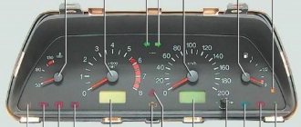
The location of instruments and warning lamps in the instrument cluster is shown in.
The following instruments and indicators are installed in the instrument cluster.
| 1 – electronic tachometer shows the engine speed. The scale has divisions from 0 to 70, the division value is 2.5. To find out the crankshaft rotation speed in min–1, you need to multiply the tachometer reading by 100. |
| 2 – on-board computer display a – fuel level indicator; b – total mileage counter; c – coolant temperature indicator in the engine cooling system; g – hours. |
To set the time, turn on the ignition and select the mode for displaying the total mileage and time. After this, set the exact time with button 8 (see). A long press on the button allows you to quickly change the hours and minutes. By briefly pressing the button, you change minute by minute.
| 3 – the speedometer shows how fast the car is currently moving. The scale has divisions from 0 to 200 km/h, the division value is 5 km/h. |
| 4 – control lamp for turning on fog lights. |
| 5 – warning light for open doors. |
| 6 – reserve. |
| 7 – indicator lamp for turning on the rear fog lights. |
| 8 – reset button for the daily mileage counter. To reset the readings, press and hold the button. |
| 9 – the warning lamp for turning on the parking brake and the state of the brake system (with a red filter) lights up when the ignition is turned on in the event of an excessive decrease in the level of brake fluid in the reservoir of the master cylinder or when the parking brake lever is raised. |
| WARNING Do not drive a vehicle with the warning light on. |
| 10 – reserve. |
| 11 – warning lamp for engine overheating (with a red filter). If the lamp lights up, you must stop, let the engine cool and eliminate the cause of overheating. |
| 12 – the engine start immobilizer system warning light lights up after turning on the ignition for approximately 3 s. When the lamp goes out, you can start the engine. If, after turning on the ignition, the lamp flashes or remains on, then the system is faulty and you need to contact a service station. |
| 13 – the indicator lamp for turning on the turn indicators (with a green filter in the form of arrows) lights up with a flashing light when the turn indicators or hazard warning lights are turned on. Flashing of the warning lamp at double frequency indicates a burnt-out lamp in any direction indicator. |
| 14 – the signal lamp for the minimum fuel reserve in the tank (with an orange filter) is constantly on when the remaining fuel in the tank is about 5 liters. |
| WARNING Avoid driving on reserve fuel whenever possible. Operation of the electric fuel pump in the absence of a continuous fuel supply with air entering the system will lead to pump failure! |
| 15 – warning lamp for emergency drop in oil pressure (with a red filter) lights up when the ignition is turned on and warns that the pressure in the engine lubrication system is below normal. Immediately after starting the engine, the lamp should go out. |
| WARNING Driving a vehicle with the warning light on is prohibited, as it will cause engine damage. |
| 16 – the battery discharge warning lamp (with a red filter) lights up when the ignition is turned on. Immediately after starting the engine, the lamp should go out. The lamp burning or glowing at full intensity while the engine is running indicates a lack of charging current caused by a malfunction of the generator or voltage regulator, and weak tension (or breakage) of the auxiliary drive belt. |
| WARNING Do not drive a vehicle with the lamp on, as, in addition to the battery being completely discharged, this may indicate a short circuit in the charging circuit, which can lead to a fire. |
| 17 – warning lamp for the engine management system (with an orange filter). Lights up when the ignition is turned on and lights up when the engine is started. Immediately after starting the engine, the lamp should go out. If the lamp comes on while the engine is running, it indicates a malfunction in the engine management system. In this case, the control unit switches to the backup program, which allows you to continue driving. When the lamp lights up, you must check the electronic control unit using the self-diagnosis function and eliminate the fault. |
| WARNING Long-term operation of the vehicle with the lamp on is not recommended, as it can lead to increased fuel consumption, deterioration of the vehicle's traction characteristics and engine breakdowns. |
If the lamp flashes, it means that there is no stable sparking in the ignition system. Reduce engine speed until the lamp goes out. As soon as possible, contact a service station or have the problem repaired.
| 18 – indicator lamp for turning on the heated rear window (with a yellow filter). |
| 19 – the indicator lamp for turning on the main beam of the headlights (with a blue filter) lights up when the main beam of the headlights is turned on. |
| 20 – warning light for disabling the front passenger airbags. |
| 21 – the driver’s seat belt warning light comes on at a speed of more than 10 km/h if the driver’s seat belt is not fastened. |
| 22 – airbag malfunction warning light (with a red filter). Functions if an airbag is installed in the steering wheel hub of the vehicle. Lights up when the ignition is turned on if there is a malfunction in the airbag system. |
| WARNING If the warning light comes on, contact a car service immediately. In addition to possible failure in an emergency, the airbag may unexpectedly deploy while driving, leading to serious consequences. |
| 23 – warning lamp for a malfunction of the anti-lock brake system (with a yellow filter). Functions if the car is equipped with an anti-lock braking system. Lights up for 3 seconds when the ignition is turned on (lamp 9 lights up at the same time), after which it should go out. |
| WARNING If the lamp does not go out, contact a car service, since braking in all cases occurs without the participation of the anti-lock braking system. |
| 24 – the indicator lamp for turning on the low beam headlights (with a green filter) lights up when the low beam headlights are turned on. |
↓ Comments ↓
Section 1. Vehicle design
General information about the vehicle Vehicle registration data Vehicle keys Controls Heating (air conditioning) and interior ventilation Doors Seat belts Seats Rear view mirrors Interior lighting Hood Gearbox control lever
Section 2. Recommendations for use
Safety rules and recommendations What you need to have in your car Running in the car Operating the car during the warranty period Preparing the car for departure
Section 3. Problems along the way
The engine will not start Malfunction of the fuel injection system Idle has disappeared Interruptions in the engine The vehicle moves jerkily The vehicle does not accelerate well The engine stalls while driving The oil pressure has dropped The engine is overheating The battery is not recharging The engine is started from external power sources Faulty electrical equipment Extraneous knocking noises Problems with the brakes Punctured wheel
Section 4. Maintenance
General provisions Daily maintenance (EO) First maintenance (MOT-1) Second maintenance (MOT-2)
Section 5. Engine
Design features Removing and installing mudguards and engine crankcase protection Replacing the suspension mounts of the power unit Installing the piston of the first cylinder to the TDC position of the compression stroke Replacing and adjusting the belt tension, replacing the tension roller of the gas distribution mechanism drive Adjusting the clearances in the valve drive Removing, installing and troubleshooting the flywheel Replacement engine seal parts Cylinder head Removal and installation of the engine Engine lubrication system Engine cooling system Exhaust system Power supply system
Section 6. Transmission
Clutch Gearbox Front wheel drives
Section 7. Chassis
Front suspension Rear suspension Checking and adjusting wheel alignment angles
Section 8. Steering
Design features Possible malfunctions of steering without hydraulic booster, their causes and methods of elimination Possible malfunctions of steering with hydraulic booster, their causes and methods of elimination Steering column Steering rods Steering mechanism
Section 9. Brake system
Features of the device Possible malfunctions of the brake system, their causes and solutions Bleeding the hydraulic drive of the brake system Checking and adjusting the brake pedal Master brake cylinder Vacuum brake booster Brake force regulator in the hydraulic drive of the rear brakes Replacing hoses and pipelines of the hydraulic brake drive Brake mechanisms of the front wheels Brake mechanisms of the rear wheels Parking brake
Section 10. Electrical equipment
Design features Diagnostics of malfunctions of on-board electrical equipment Mounting blocks Battery Generator Starter Ignition switch (lock) Engine control system Lighting, light and sound alarm Windshield wiper Removal and installation of the windshield washer Removal and installation of the electric motor of the radiator fan of the engine cooling system Electric heating of the rear window Removal and installation cigarette lighter socket Instrument cluster Immobilizer Instrument panel switches Car audio system Replacement of sensors and switches
Section 11. Body
Design features Possible body malfunctions, their causes and solutions Removal and installation of bumpers Removal and installation of radiator lining Removal and installation of wheel mudguards and fender liners Removal and installation of the front wing Hood Removal and installation of the air intake box grille Doors Trunk lid Removal and installation of the fuel filler hatch cover tank Seats Removal and installation of floor tunnel lining Passive safety system (SRS) Rear view mirrors Instrument panel Heater and air conditioner Interior fittings Removal and installation of interior linings Removal and installation of trunk lining Replacement of fixed body glazing Body care
Section 12. Wheels and tires
Technical characteristics Marking of rims Marking of tires Replacing wheels Tire break-in Tire storage Wheel balancing Snow chains Spare wheel Checking tire pressure Checking tire profile Checking valve Checking radial and lateral runout of rims
Section 13. Purchase of spare parts
Engine oil Lubricants Coolants Brake fluid Fuel filter Air filter Engine oil filter Spark plugs
Section 14. A trip to the service station
Section 15. Winter operation of the vehicle
How to prepare a car for winter Recommendations for starting the engine in severe frost What is useful to buy for winter Useful winter tips
Section 16. Preparation for technical inspection
Recommendations List of malfunctions and conditions under which the operation of vehicles is prohibited Changes to state standards regulating the maximum permissible content of harmful substances in the exhaust gases of motor vehicles
Section 17. Tips for a novice auto mechanic
Safety precautions when carrying out repair work Tools Before starting work Restoring threaded connections Tips for body repair
Applications
Appendix 1. Tightening torques of critical threaded connections, N m Appendix 2. Lamps used on a car Appendix 3. Spark plugs used on a car Appendix 4. Air pressure in tires
Electrical circuit diagrams
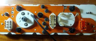
Diagram 1. Battery charging circuit: 1 – starter; 2 – generator; 3 – electrical wiring connector for the engine compartment/interior (monoblock); 4 – instrument cluster Diagram 2. Fuel pump and fuel level sensor: 1 – instrument cluster; 2 – electrical wiring connector for the engine compartment/interior (monoblock); 3 – electrical wiring connector for the instrument panel/left rear part of the body; 4 – fuel pump and fuel level sensor; 5 Diagram 3. Engine control system: 1 – 597V fuse box in the engine compartment (see Fig. 10.2a and 10.2b); 2 – relay block 784 in the engine compartment, relay 700 (see Fig. 10.2a and 10.2b); 3 – injector of the 1st cylinder; 4 – fuse box in the passenger compartment (see fig. 4. Engine starting system: 1 – battery; 2 – starter; 3 – engine compartment/cabinet electrical wiring connector (monoblock); 4 – ignition switch (lock) Diagram 5. Turn indicators and alarm system: 1 – interior switching unit; 2 – electrical wiring connector for the instrument panel/left rear part of the body; 3 – right rear light; 4 – right front turn signal; 5 – right indicator repeater Diagram 6. Side light: 1 – fuse box in the cabin (see Fig. 10.1); 2 – electrical wiring connector for the instrument panel/left rear part of the body; 3 – side light of the left headlight; 4 – left rear lamp; 5 – license plate lamp; 6 – Diagram 7. High beam : 1 – fuse box 597A in the engine compartment (see Fig. 10.2a and 10.2b); 2 – switch lever for external lighting and direction indicators with a button for turning on the sound signal; 3 – fuse box in the passenger compartment (see Fig. 10.1); 4 Diagram 8. Electrically heated rear window: 1 – fuse box in the passenger compartment (see. rice. 10.1); 2 – instrument cluster; 3 – electric heating of the rear window; 4 – electrical wiring connector for the instrument panel/left rear part of the body; 5 – electric heating switch for Scheme 9. Electric fan of the heating and ventilation system of the cabin: 1 – fuse box in the cabin (see Fig. 10.1); 2 – relay 233 (see Fig. 10.2a and 10.2b); 3 – wiring connector for the electric fan of the cooling system/instrument panel; 4 – electric fan Diagram 10. Front fog lights: 1 – instrument cluster; 2 – switch lever for external lighting and direction indicators with a button for turning on the sound signal; 3 – fuse box in the passenger compartment (see Fig. 10.1); 4 – relay block 299 in the engine compartment Diagram 11. Electric mirror drive: 1 – fuse block in the passenger compartment (see Fig. 10.1); 2 – control unit for external rear view mirrors; 3 – electric drive of the left outside rear view mirror with heating; 4 – electric drive of the right outside rear mirror Diagram 12. Low beam: 1 – fuse block 597A in the engine compartment (see Fig. 10.2a and 10.2b); 2 – switch lever for external lighting and direction indicators with a button for turning on the sound signal; 3 – fuse box in the passenger compartment (see Fig. 10.1); 4 Diagram 13. Front door power windows: 1 – front passenger door power window switch; 2 – electric motor for window lift of the front passenger door; 3 – driver’s door window lift motor; 4 – block before Scheme 14. Electric fan of the heating (air conditioning) system and interior ventilation: 1 – fuse box in the passenger compartment (see Fig. 10.1); 2 – relay 233 (see Fig. 10.2a and 10.2b); 3 – electrical wiring connector for the engine compartment/interior (monoblock); 4 – electric fan Diagram 15. Sound signal: 1 – lever of the switch for external lighting and direction indicators with a button for turning on the sound signal; 2 – fuse box in the passenger compartment (see Fig. 10.1); 3 – sound signal; 4 – fuse block 597A in the engine compartment (see Diagram 16. Central locking system: 1 – interior switching unit; 2 – electrical wiring connector for the instrument panel/left rear part of the body; 3 – electric drive for the right rear door lock; 4 – electric drive for the left rear door lock doors; 5 – electric drive Diagram 17. ABS control system: 1 – fuse box in the passenger compartment (see Fig. 10.1); 2 – fuse box 597C in the engine compartment (see Fig. 10.2a and 10.2b); 3 – ABS ECU ; 4 – electrical wiring connector for the instrument panel/left rear part of the body; 5 – speed sensor Diagram 18. Windshield wiper and washer, headlight washer: 1 – windshield washer pump; 2 – instrument cluster; 3 – interior switching unit; 4 – electric motor windshield wiper; 5 – wiper and washer switch lever Diagram 19. Interior lamp: 1 – interior switching unit; 2 – electrical wiring connector for the instrument panel/left rear part of the body; 3 – interior lamp; 4 – driver’s door limit switch; 5 – limit switch of the right front door; Diagram 20. Connecting the speakers of the acoustic system: 1 – car radio; 2 – electrical wiring connector for the engine compartment/interior (monoblock); 3 – fuse box in the passenger compartment (see Fig. 10.1); 4 – cigarette lighter; 5 – vehicle speed sensor; 6 – right front Diagram 21. Rear fog lamp: 1 – fuse block 597A in the engine compartment (see Fig. 10.2a and 10.2b); 2 – switch lever for external lighting and direction indicators with a button for turning on the sound signal; 3 – fuse box in the passenger compartment (
Renault Logan dashboard description of indicators
The design of the ventilation system nozzles is unusual, but at the same time practical, since this design has an increased ability to correctly distribute air flows inside the cabin, thereby facilitating the operation of the air conditioning unit. Among the main control elements present on the panel and causing some complaints from demanding Renault Logan owners are the regulators: After starting the engine, the warning light should go off.
If the warning light remains on, let the engine idle for one or two minutes - the temperature should drop. If the indicator continues to light, check the cooling system; 10 - not used; 11 — indicator for turning on the parking brake and insufficient fluid level Renault Logan instrument cluster in the hydraulic reservoir of the brake system lights up red when the parking brake is applied and the level of brake fluid in the reservoir decreases; 12 - the turn signal indicator lights up with a flashing green light when the left or right turn indicators are turned on; Renault Logan instrument cluster is turned on when the hazard lights are turned on; 13 - the engine management system malfunction indicator lights up orange when the ignition is turned on and then goes out.
If the lamp is constantly on, you need to contact a service station. Some vehicles do not use a signaling device; 14 - the immobilizer status indicator lights up red.
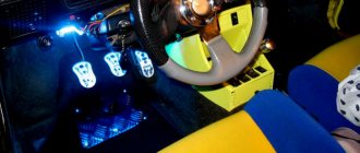
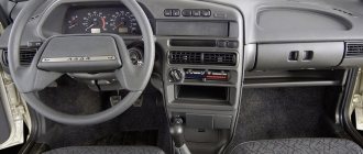
It not only has space for installing a radio with a radio in cars with basic equipment, in others they are already installed and two air vents with deflectors. Under the radio on the center console there is its own instrument panel with controls. There is a button for turning on the heated rear window, control buttons for the left and right electric windows, and knobs for adjusting the direction of the air blowing. There is also an air temperature regulator and an air conditioning control knob if one is installed.
The center console instrument panel has a hazard warning button. Over the past couple of years, the Renault Logan car has undergone a number of changes for the better. Renault Logan instrument cluster also touched the interior.
To remove them from memory and leave the self-diagnosis mode, press the Renault Logan instrument cluster button located on the instrument panel for a few seconds.
This mode allows you to find out the momentary consumption even when the car is standing still. Controls and instrument panel 1.
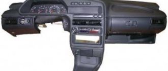
Side deflector. Side air nozzle. Dashboard.
Renault Logan dashboard description of indicators
The space reserved for installing the driver's airbag. Central deflectors. Central air nozzle. Space reserved for installation of a passenger airbag. Glove box.
Hazard switch. Control of electronic door locks. Space for installing an audio system or storage compartment. Air conditioner control panel. Switch for heated rear window and exterior mirrors.
Rear window control button. Power window switch. Rear window lock switch.
Space reserved for installing an ashtray or glass holder. Cigarette lighter or socket for additional equipment. Parking brake.
LPG button. Gear shift lever. Egnition lock.
Audio system remote control. Regulator of the direction of light beams in height.
Hood release lever. ECO mode switch. Adjuster for exterior rear view mirrors.
Logan dashboard: icon designation
Some users, when buying a used car, do not understand what the indication in the form of a cardiogram and other pictures mean. For more convenient understanding, the meaning of the signs is given in the table with photos.
Logan 1 dashboard icons
The first generation started in 2006 and has been actively used by motorists since then. Indicators and icons on the vehicle's dashboard display the status of the modules in real time and indicate to the driver any malfunctions or errors.
The machine contains a minimum set of basic and additional equipment, which makes it possible to limit the number of indicators and instruments.
A special feature of the icons is that when the engine starts, all icons light up simultaneously and go out after 10 seconds. In this case, each lamp belongs to only one circuit.
Description of the icons on the Renault Logan 2 dashboard
The second modification of the car has been available since 2014 and differs from the first generation in its improved design. The car's tidy remained the same. All the lights and icons remained in their original places and retained their original appearance and meaning.
Logan 3 dashboard icons
In the third generation, more global changes took place. The design of the tidy has changed a lot, a modern cladding and several edgings have been added. It is noteworthy that no new equipment and systems appeared in the car. Common icons have the same meaning and appearance.
Possible malfunctions and ways to eliminate them
The dashboard on Renault Logan and Sandero is quite reliable. Problems with devices occur relatively rarely. In some cases, malfunctions of other vehicle components are mistaken for problems with indicators.
Thus, for adequate operation of the speedometer, tachometer and other elements, stable operation of the corresponding vehicle sensors is necessary. If they display incorrect information, a breakdown is possible with the sensors.
Also, a common problem with these and other cars is a violation of the integrity of the wiring, which could occur during the repair of other components of the car. You can check the wiring using standard instruments.
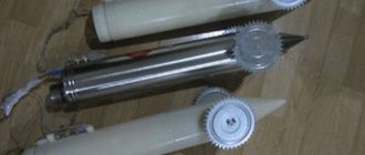
If one of the panel elements has really become unusable for you, you can replace it either separately or as a whole. Lamps are especially easy to replace, while the speedometer and tachometer will be more difficult to replace.
The video below demonstrates the process of replacing some light bulbs (the author of the video is Aleksei Suchkov).
Also, you can completely dismantle the old panel and install a new one.
Replacing light bulbs in the Renault Logan console
And at the moment, a little about what I want to share with you, directly speaking about how to change light bulbs
in the console, those that.
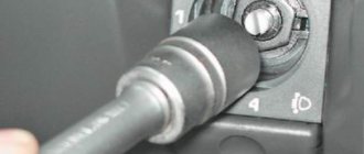
V. switching of close/far beam (non-fixed position). Replacing the radiator on Laguna 1 with comparison and selection of Renault Laguna - forum section. Replacing light bulbs in the heater block on Renault Logan before 2010. When you hold the lever, the high beam glows;
VI _ rear fog lights are on (side lights will be on);
On vehicles equipped with fog lights, when the ring is turned to position VI, the fog lights turn on. Details on how to remove the instrument panel on a Renault Logan yourself for repair work, video and detailed photos of the removal process. To turn on the rear fog light, you need to turn the ring to the appropriate position (the side lights are on).
VII. button to turn on the sound signal. In the video I How to remove Replacing the high panel of a VAZ 2108-21099 with a euro panel of a VAZ. What indicators does the Renault Logan dashboard have? dashboard on Renault Logan and. To turn on the sound signal, press the button.
When the lever is moved to position I, also called II, in the arrangement of devices, indicator light 13 lights up with a flashing light (Fig. 1.8). Replacing a light bulb in a Renault cigarette lighter When the control wheel is returned to the straight-line position, the lever is automatically set to its initial position. How to replace the air filter On a Renault Logan Renault car there are 16 valves;. Removing the instrument panel panel on a Hyundai Accent When changing lanes, to turn on the turn signal, simply press the lever in the direction of position I or II only until you feel tangible resistance, without fixing the lever. Replacing instrument panel and air conditioner bulbs on Renault Laguna 1.8 How to replace. When released, the lever will return to its original position.
Instruments on the center console
The dashboard also includes a center console. It not only has space for installing a radio with a radio (in cars with basic equipment, in others they are already installed), but also two air vents with deflectors. Under the radio on the center console there is its own instrument panel with controls. There is a button for turning on the heated rear window, control buttons for the left and right electric windows, and knobs for adjusting the direction of the air blowing. There is also an air temperature regulator and an air conditioning control knob (if one is installed). The center console instrument panel has a hazard warning button.
Over the past couple of years, the Renault Logan car has undergone a number of changes for the better. They affected not only the body, making it more stylish and a little more “aggressive” thanks to a new radiator grille and a modified front bumper. The changes also affected the interior. The front panel, on which the instruments and their controls are located, has also changed somewhat. The display moved from its center to the right, into the same chrome ring as the tachometer and speedometer. This has made the instrument panel more stylish and possibly more convenient - now the steering wheel in any position does not block the view of the display screen.
The center console has also changed somewhat. The power window buttons disappeared from it. They moved to the front doors (two for the driver and one for the passenger), which made controlling the windows much more convenient. Some skilled amateurs install indicators for unfastened seat belts and open doors on their cars, which makes driving safer.
The dashboard of a budget car Renault Logan is an integral part of the image of this car as a practical and inexpensive car. The process of removing and installing it is also not a big problem.
Main dashboard sensors
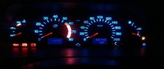
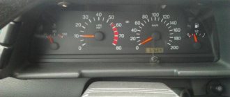
Like any other car, Logan's dashboard has a tachometer and speedometer. But the tachometer, unlike some other cars, has a scale that is a multiple of ten. That is, if the arrow on the tachometer points to 20, this means that the crankshaft rotation speed is 2000 rpm. On the speedometer in its lower part, not occupied by the speed scale, there are luminous sensors for turning on the low and high beams, as well as the rear fog lamp.
The dashboard has four deflectors - circles, with the help of which the strength and direction of the air ventilating the interior of the car and blowing the driver and front passenger are regulated. The dashboard has a liquid crystal display that displays the time and mileage. The fuel level in the tank (on the left) and the coolant temperature (on the right) are also shown here in the form of stripes. When the gray stripes on the left disappear, it means that there are 5-6 liters of fuel left in the tank. It should be enough to get to the nearest gas station.
Using the button built into the instrument panel at the bottom left of the speedometer, you can set the correct time on the display, check the car's daily mileage, and check the instantaneous fuel consumption in the engine. In addition, at idle, this button allows you to test how the instrument panel works - the tachometer with speedometer and all sensors with warning lights. Sometimes it happens that after refueling the car, the empty tank indicator remains on. Using the named button and turning on the test mode, you can turn it off.
A small screen with indicator lights is located below the display. Indicators from top to bottom left:
- minimum amount of gasoline in the tank;
- There is not enough oil in the engine crankcase, the battery is discharged.
- insufficient coolant level or overheated;
- The parking brake is on.
The middle column of signal indicator lights has the following meanings: two arrows indicate the inclusion of a right or left turn signal. The middle red dot lights up a couple of minutes after the ignition is turned off and the key is removed from the lock. This means that the anti-theft locking device has turned on, reading the key code when you press the “Open” button on the key fob.
The lower middle light is an indicator of increased toxicity of exhaust gases (exhaust). It sometimes lights up when the gas tank is filled with fuel with a lower octane rating than the car manufacturer recommends. Some people think that you should not pay attention if this light is on. But in fact, the indicator can tell the car owner that his fuel consumption has increased.
Possible faults
If the car’s operation is disrupted, the dashboard warns about this, and quite often this is associated with the failure of such system elements as:
- Temperature sensor
- Speed sensor
- Circuit breakers
This problem can be solved by simply replacing these sensors. Particular attention should be paid to the indicator in the form of an engine, it is also called a check, it is responsible for the engine system, during the start of the power unit it should light up and immediately go out, if it continues to light, this warns that there is a malfunction in the engine system. If this indicator starts flashing, this may be due to an unstable spark supply, so it is advisable to reduce the speed. As you can see, the panel is quite informative, and if you know what each element is responsible for, you can quickly determine the cause of the malfunction, and to understand the designation, below is a list of icons with descriptions:
Description and location of indicators
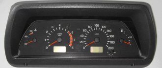
In the photo you see an instrument panel with the main indicators marked on it.
- Tachometer. It has an electronic device that displays readings from the crankshaft rotation sensor. The size of one division is 2.5, the range of values is from 0 to 70. To obtain the real value of rotations in one minute, you need to multiply the value by 100.
- BC display. Has several separate indicators. On the left is an indicator of the amount of gasoline, in the center at the top is an indicator of the total distance traveled by the car. On the right is the coolant temperature indicator. There is a clock in the bottom center. The setting is made with the ignition on, determine the mode for displaying time and mileage, then use button 8 to set the desired value.
- Speedometer. Displays the vehicle speed. The upper level is 200 km/h, each division is 5 km/h.
- Lamp indicating that the foglights are turned on.
- Warning light - indicates that the doors are not closed.
- Reserve.
- This indicator indicates the rear fog lights.
- Daily mileage reset button. To activate it you need to press it a little.
- Parking brake warning light and general brake system condition indicator. May light up when the ignition is activated if the brake fluid level in the system is dangerously low.
- Reserve for Logan diesel models.
- Warning lamp for engine overheating.
- Engine blocking warning light. It should go out 3 seconds after ignition. If it continues to light, there is a critical malfunction in the system.
- Direction indicators. If the indicator starts flashing, it means that a bulb in one of the turn signals has broken.
- The minimum fuel reserve indicator begins to light constantly when there are about 5 liters left in the tank.
- Indicator of emergency drop in oil level.
- The battery discharge indicator lights up briefly when igniting, and should go out after the engine starts.
- Engine control lamp. Normally, it should light up after ignition and continue to light until the engine is fully started. If it lights up and the engine is running, then there is something wrong with its control system. You will be able to continue driving on the backup program, but the car requires repairs.
- Heated rear window.
- High beam indicator.
- Front passenger airbag deactivation signal.
- The driver's seat belt warning light comes on at speeds over 10 km/h.
- Airbag malfunction lamp.
- Malfunction of the anti-lock brake system.
- Lamp for low beam headlights.
Photo gallery “Renault car panel”
Video about replacing the dashboard
1 - Tachometer (scale division unit - 100 rpm).
2 - Fuel level indicator.
3 - Multifunction display: odometer, trip odometer, time setting or on-board computer.
4 - Coolant temperature gauge.
5 — Speedometer.
6.— Signal light for turning on the rear fog lights.
— Signal light for turning on the front fog lights.
— Warning light for door not closed.
7 - Multifunction button:
Controlling data output to the display. When you briefly press the button, you switch from the total mileage/time display to the trip mileage/time display or vice versa. Resetting the trip odometer to zero. Display the trip odometer readings, press the button and hold it down for a while. Setting the exact time.
— Signal light for minimum fuel level in the tank.
— Signal light for turning on the direction indicators.
— Coolant temperature warning light.
— Warning light for low engine oil pressure.
— Warning light for electronic engine immobilizer.
— Signal light for electronic system malfunction/signal light for preheating (diesel engine).
— Warning light for low battery.
— Warning light for the exhaust gas emissions reduction system.
— Signal light for parking brake activation and brake system malfunction.
— Signal light for low beam headlights.
— Signal light for turning on the high beam headlights.
— Signal light for anti-lock braking system malfunction.
— Airbag warning light.
— Warning light for unfastened driver's seat belt.
— Signal light for disabling the front passenger airbag.
— Signal light for turning on the heated rear window.
Renault Logan is a budget, but practical and multifunctional car. This is clearly evidenced by the ergonomic instrument panel, which is equipped with a considerable number of sensors, indicators and various lights. They participate in the management and control of transport, monitor the condition of vehicle systems and mechanisms, and regulate various processes in them. But even highly practical elements eventually become unusable, and sensors and fuses burn out. In this case, you will need to replace the light bulbs in the dashboard, which, if you know the features, you can do it yourself.
All models (with 1.4 and 1.6 l engines) and generations (2005-2009, restyling 2009-2016, 2014-2017) were created with special attention to a modern, sophisticated and optional type of tidy.
You can find many photos online that show the designations of all the indicators, lamps and torpedo icons, as well as a video with a detailed description of the functions.
Front brake pads Renault Logan 2 (2018-2021) restyling
2018-2021
Notify of receipt
Your request has been accepted!
You will receive a notification when the product goes on sale to your contacts.
– required to be filled out
0 ₽
Not in stock
more details
2018-2021
Notify of receipt Your request has been accepted! You will receive a notification when the product goes on sale to your contacts.
– required to be filled out
0 ₽
Not in stock
more details
2018-2021
Notify of receipt Your request has been accepted! You will receive a notification when the product goes on sale to your contacts.
– required to be filled out
0 ₽
Not in stock
more details
2018-2021
Notify of receipt
Your request has been accepted!
You will receive a notification when the product goes on sale to your contacts.
– required to be filled out
0 ₽
Not in stock
more details
2018-2021
Notify of receipt Your request has been accepted! You will receive a notification when the product goes on sale to your contacts.
– required to be filled out
0 ₽
Not in stock
more details
2018-2021
Notify of receipt Your request has been accepted! You will receive a notification when the product goes on sale to your contacts.
– required to be filled out
0 ₽
Not in stock
more details
FRONT DISC BRAKE PADS Renault Logan 2 restyling
000 537B-SX
1.6 (102 hp), Petrol, 1.6 (82 hp), Petrol, 1.5 dCi (84 hp), Diesel, 1.6 (113 hp), Petrol, 410602396R, with anti-squeak plates STELLOX
Manufacturer: STELLOX
Release period: 2018-2021
2018-2021
more details
2018-2021
Notify of receipt Your request has been accepted! You will receive a notification when the product goes on sale to your contacts.
– required to be filled out
0 ₽
Not in stock
more details
2018-2021
Notify of receipt Your request has been accepted! You will receive a notification when the product goes on sale to your contacts.
– required to be filled out
0 ₽
Not in stock
more details
Installation instructions
New standard trim
To dismantle the old part and install a new one, you need to perform the following procedure:
- first disconnect the wires from the battery, negative first;
- partially remove the door seal;
- remove the decorative panel from the left front pillar;
- Unscrew the bolts on both sides of the panel;
- then remove the small covers located at the bottom edges of the instrument panel;
- there are bolts under them, unscrew them, then remove the headlight range control knob;
- Unscrew the bolts that are located under the corrector handle;
- remove the upper steering column cover;
- unscrew the bolt, disconnect the wiring connectors, and then remove the steering column switches;
- now unscrew the bolts above the column;
- remove the visor of the shield;
- Unscrew the shield bolts, disconnect the wiring connectors and remove it;
- remove the radio;
- now unhook from below and completely remove the central decorative wiring, disconnect the wires;
- remove heating and air conditioning system regulators;
- now dismantle the heating and air conditioning regulator, unscrew one bolt at the top and two at the bottom;
- then disconnect the diagnostic connector;
- completely remove the instrument panel, disconnect the wiring block;
- unscrew the bolts securing the front passenger airbag, remove the wiring connector to it;
- then remove the rivets from the glove box and the cover;
- Installing a new panel is done in the reverse order.
Indicator color codes
The dashboard of your current or future car, as mentioned above, has special indicators.
The dashboard will not stop warning you until you fix the problem in your car. It should also be noted that red does not always indicate a serious malfunction. The instructions say that this color is often used as a reminder to the vehicle owner, for example, if the parking brake is not turned off. In this case, driving the older model will simply be impossible, but in modern models, like the Renault Duster, this does not interfere with movement.
The description of the lights on the dashboard also includes yellow or orange colors. They indicate that a specific mechanism of the machine needs repair work or maintenance.
For the most part, according to practice and description, if the yellow light begins to flash, then the driver is obliged to pay attention to this and promptly contact a service center with specialists to carry out diagnostics and eliminate the malfunction, so that nothing interferes with driving the vehicle in the future
The dashboard can also display blue or green symbols, which, as the description says, turn on to inform the car owner that the vehicle is operating normally.
Having examined the colors of the indicator lights and understood what they signal, you can safely move on to the next point - deciphering the icons. You need to start with the most serious and important designations and indicators.
Advantages and disadvantages of the front instrument panel
The front instrument panel of this car is a symbiosis of practicality and efficiency in production. The controls on the front instrument panel are located quite logically and do not require much time to get used to. The layout of the main controls is chosen quite well, in comparison with competitors, it has a number of pros and cons in its structure:
- the presence of a sufficiently deep “glove compartment” is one of the positive aspects of Renault Logan, however, the lack of finishing materials, “bare plastic”, is at the same time a negative factor;
- The layout of the instrument panel on the front panel is quite logical and predictable; these elements are clear and easy to read under any lighting level and weather conditions;
- The ventilation nozzles have an unusual, but at the same time, very practical shape in the form of circles with an adjustable airflow plane. This ventilation scheme, carried out through the instrument panel, allows for the most efficient distribution of air flows, which contributes to more efficient operation of the heating and air conditioning system;
A feature of Renault Logan, in this case, is the negative angle of inclination relative to the driver. This significantly reduces the visibility of the control keys, which can affect not only control comfort, but also driving safety. This scheme in the second generation of Renault Logan received a number of changes, and this negative point was eliminated;
Also, the disadvantages often include the poor quality of the panel plastic, but in the budget car segment this cannot be considered any disadvantage.
Replacing light bulbs
Instructions for pinout the board and connection diagram, as well as the location of elements on the dashboard for Logan depend on the year of manufacture. You should only disassemble the panel, change indicators, and replace lamps if you have experience and knowledge of the technical features of the car. Firmware and wire layout may vary depending on the configuration.
To replace faulty light bulbs and indicators, you must remove the panel. The disassembly procedure is as follows:
- Remove the casing on the steering column; to do this, remove the bolts from its body;
- Take out the cladding, the fastenings of which are the clamps;
- Remove the screws securing the casing from the bottom;
- After removing the cover, unscrew the screws located on both sides;
After replacing non-functioning elements with new ones, assembly is performed in the reverse order.
Changing indicators and lamps yourself, disassembling the instrument panel and changing the colors of light bulbs does not cause any difficulties for the average driver. On the Internet you can find a large number of step-by-step instructions and guides to action, which describe in sufficient detail disassembling the panel, removing faulty elements, changing the color of the lamps from red to any other, removing plugs and other parts of the torpedo.
Do not forget that when carrying out any repair work, before you start using the car, you should test the panel and set the correct characteristics. Failure to perform a performance test may affect driving safety.
Today, not a single civilian car can do without an instrument panel. The practical Renault Logan is no exception. If the owner needs to dismantle or install this integral attribute of the interior, then performing the procedure will not cause any particular difficulties. In this article you will learn everything about the instrument panel description and symbols, including a description of the indicators.
Color designations
When driving a car, the main thing is to understand what the signal that appears warns about, for example, a red color indicates a serious malfunction, so you need to be as careful as possible in eliminating this problem, and until it is resolved, the signal will not disappear. In addition to the red indicator, there are orange and yellow ones, they warn that a certain element requires repair or maintenance. Therefore, if a yellow light comes on, it is advisable to eliminate the reason why it came on as soon as possible; you can do this yourself, or contact a specialist.
The Renault Duster dashboard also has green and blue indicators, which signal to the driver that the vehicle is working properly.
How to dismantle the panel and install it in place in Logan?
To complete the removal procedure, you need to follow several specific steps (given below).
- First, we dismantle the entire list of easily fixed elements, namely:
- instrument panel;
- steering column housing, etc.
- We begin removing the panel from the left side in the area where the air deflector is located. Here the assembly is held in place by plastic clips. They are quite fragile, so we perform the indicated manipulation with extreme care.
- Now we will implement similar actions with the right side of the panel.
- The next step is to remove the instrument panel. It is secured with several screws. Removing it itself may bring some difficulties due to the peculiarities of how this element fits in its place.
- Now we proceed to dismantling the center console.
- The radio and frame are held together with latches. Prompt removal will require some skill, otherwise the process may be delayed.
- The console itself is fixed with special plastic clips, after carefully removing which it is possible to remove the entire element (console).
- Let's move on to the central deflectors of the heating system. The first phase is characterized by the rounded outlines of the nozzles, and in the second they turned into rectangular components.
Only now is it becoming possible to remove the entire panel.
The installation procedure of the unit we are considering implies a strictly reverse sequence in relation to the dismantling process.