Why does a diesel engine need a governor?
There is no control rack position for a diesel engine that would allow the diesel engine to accurately maintain its speed without the aid of a governor. At idle, for example, without a speed controller, the engine speed will either drop until the engine stops, or will continue to increase, eventually causing the engine to self-destruct.
The latter possibility is due to the fact that the diesel engine operates with excess air, which means that there is no effective throttling of the mixture entering the engine as its speed increases.
For example, if a cold engine is started and left to idle while the initial amount of fuel continues to be injected, then the characteristic friction will soon begin to decrease. The same applies to the engine load from the units driven from it, such as a generator, air compressor, fuel injection pump, etc. This means that if the position of the control rack remains unchanged and the rack is not retracted to reduce the amount of fuel supplied (as a governor would do), then the engine speed will increase more and more (due to the above drop in friction) until it reaches the point self-destruction. In other words, it is mandatory that the diesel engine be equipped with a speed controller. Currently, in-line injection pumps use either mechanical (centrifugal) regulators or an electronic diesel control (EDC) system.
Pneumatic regulators controlled by intake manifold pressure were previously installed on small fuel injection pumps. They had to be abandoned as a result of increased demands on the accuracy of regulation and on the operation of the regulator.
What is the injection pump used for?
The main difference between a gasoline unit is the ignition of the combustible mixture inside the cylinders. In a gasoline engine, the mixture is ignited by spark plugs. In a diesel engine, the mixture spontaneously ignites under compression. The injection pump is needed for the timely supply of diesel fuel to the cylinders at the moment of compression.
By design, injection pump pumps differ as follows: in-line type, main type and distribution type. In an in-line engine, diesel fuel is pumped into each cylinder from its own pair of plungers. The distributor provides all cylinders with one or two pairs of plungers. Mainline devices are used to pump diesel fuel into the fuel accumulator.
Remember, injection pump and injectors are the main elements of the diesel ignition system. They are present in most diesel units and are of the electronic type.
Setting the fuel injection timing on the D-240 MTZ 82 (80) engine
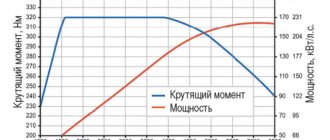
The often-called concept of “ignition adjustment” or “ignition installation” is unacceptable and technically illiterate in relation to the D-240 diesel engine of the MTZ-80(82) tractor, given that the fuel ignites under the influence of pressure at the end of the “compression” stroke in an atomized state. In relation to a diesel engine, this concept is called “fuel injection unit”. To operate a diesel engine and produce torque and power with the corresponding technical indicators, the fuel supply is synchronized with the operation of the piston group in the “compression” strokes in each individual cylinder with an appropriate repeating frequency. Correct adjustment ensures that fuel is injected into the cylinder at a certain moment - with a slight advance before the top dead center in the “compression” stroke of the working cycle.
Injection too early disrupts the thermal balance of air and ignitable atomized fuel, increasing ignition time. The result of late injection will be incomplete combustion of fuel, accompanied by engine overheating, smoke and loss of power.
Diesel injection systems
Conceptually, internal combustion engines - gasoline and diesel - are almost identical, but there are a number of distinctive features between them. One of the main ones is the different occurrence of combustion processes in the cylinders. In a diesel engine, fuel ignites due to exposure to high temperatures and pressure. But for this it is necessary that diesel fuel is supplied directly to the combustion chambers not only at a strictly defined moment, but also under high pressure. And this is provided by diesel engine injection systems.
The constant tightening of environmental standards and attempts to obtain greater power output with lower fuel costs ensure the emergence of ever new design solutions in the diesel fuel system.
The operating principle of all existing types of diesel injection is identical. The main power elements are the high-pressure fuel pump (HFP) and the injector. The task of the first component is to inject diesel fuel, due to which the pressure in the system increases significantly. The nozzle ensures the supply of fuel (in a compressed state) to the combustion chambers, while atomizing it to ensure better mixture formation.
It is worth noting that fuel pressure directly affects the quality of combustion of the mixture. The higher it is, the better the diesel fuel burns, providing greater power output and less pollutants in the exhaust gases. And to obtain higher pressures, a variety of design solutions were used, which led to the emergence of different types of diesel power systems. Moreover, all the changes concerned exclusively the two indicated elements - the injection pump and injectors. The remaining components - tank, fuel lines, filter elements, are essentially identical in all available types.
How to set the ignition on a diesel engine
One of the main differences between a diesel engine and a gasoline engine is the principle of ignition of diesel fuel. Ignition of the fuel-air mixture in a diesel engine is realized through self-ignition of diesel fuel from contact with pre-compressed and heated air in the cylinders as a result of such compression.
Setting the ignition on a diesel engine involves changing the advance angle of fuel injection, which is supplied at a clearly defined moment at the end of the compression stroke. If the angle is set differently from the optimal parameters, then the fuel injection will be untimely. The result will be incomplete combustion of the mixture in the cylinders, which causes a destructive imbalance in engine operation.
It turns out that the ignition system of a diesel engine should be understood as the most important element of the power supply system of the power unit - the high-pressure fuel pump (HPF). In most diesel engines, it is this device, in combination with diesel injectors, that is responsible for the timely, dosed supply of diesel fuel to the engine cylinders.
Other methods of bleeding the fuel system of a diesel engine
So, above we looked at the main way to bleed a diesel fuel system. At the same time, many specialists and experienced car enthusiasts separately point out that in some cases such attempts to bleed the pump can have serious consequences for the power system.
Please note that the reason for this concern is that if there is mechanical damage, bleeding in this manner can cause irreparable damage. Let's look at other existing methods
First of all, the bolt on the fuel return line (the so-called “return”) is loosened. Next, you should carefully monitor how the fuel comes out. If air bubbles are visible, then this means that the system is airy.
If so, you can use a simple tire inflator or compressor. Next, the hose is removed from the fuel pump and the air pump hose is installed in its place. The basic idea is that pumping occurs, which allows the pressure in the system to increase. This pressure makes it possible to pump diesel fuel into the fuel pump.
So, first the fuel filter is removed and its housing is dried. Then the individual elements are wiped, then reassembled. Next you will need to locate two fittings on the filter housing. One of the fittings is needed for draining diesel fuel, and the other is suitable for pumping.
Having prepared the vacuum cleaner, you also need a regular medical syringe and a hose 30-40 cm long. For these purposes, it is recommended to use a transparent type of hose. The syringe is inserted into the hose, and the other end of the hose is put on the bleeder fitting.
Next, the piston is pulled out of the syringe, and the vacuum cleaner tube is inserted into the syringe. The main thing is to achieve reliable fixation and a tight fit. Also, the joints can be sealed by putting on pieces of hoses of different diameters, winding electrical tape, etc.
Now you can unscrew the fitting a little, after which the vacuum cleaner turns on. After a few seconds, yellowish foam can be seen in the syringe. This is a mixture of diesel fuel and air. Further pumping comes down to ensuring that the syringe is filled with clean diesel fuel instead of foam.
Let's consider another solution that allows, in some cases, to quickly pump the diesel fuel system. To do this, it is enough to completely fill the fuel filter housing with diesel fuel, after which the engine starts. Next, you need to let the engine run at high speeds, as a result of which the power system is pumped.
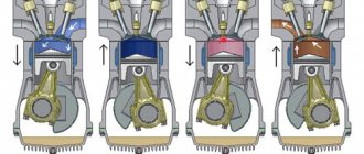
Regulator operation
There is no doubt that when a load is applied to the engine, the injection pump must always provide the engine with the required amount of fuel. All in-line injection pumps have a separate plunger pair (plunger (3) and liner (1)), also called a discharge section (element), for each engine cylinder.
The plunger is moved in the direction of fuel supply by a cam shaft driven by the engine, and returns back under the action of a return spring. Since the stroke of the plunger cannot be changed, the amount of fuel pumped can only be adjusted by changing the effective (active) stroke of the plunger.
Rice. Regulator operation
The plungers are equipped with an inclined spiral cut (channel), so that the required effective stroke is selected by turning the plunger. The rotation is carried out using a control rack (5), which is engaged with the plunger and itself moves longitudinally with the help of a regulator. Rotation of the plunger moves the helix (notch) (4) to control when the feed ends (also known as release or opening of the sleeve) and the amount of feed. Feeding begins at the moment when the upper edge of the plunger closes the inlet hole (2) in the wall of the sleeve.
In the case of maximum flow (c), no discharge occurs until the maximum effective stroke of the plunger, in other words, with the maximum possible amount of fuel supplied. With partial feed (b), the release occurs earlier depending on the position of the plunger when turning. In the final position, which is required for zero feed (a), i.e. at the moment when the engine must be stopped, the longitudinal groove of the plunger is located directly opposite the inlet hole. This means that the discharge chamber above the plunger is connected to the fuel line during the entire stroke of the plunger, i.e. fuel is not supplied.
There are several different helix configurations.
In the case of a plunger with only a bottom spiral (notch), fuel delivery begins at the same point in the upward stroke of the plunger, while the end of delivery occurs earlier or later depending on the rotation of the plunger. When the plunger has an upper spiral (notch), the start of the feed may change. There are also plungers equipped with both upper and lower ones.
General description of fuel injection pump assembly
Before assembling the fuel injection pump, it is necessary to wash and troubleshoot it. It is advisable to wash fuel pump parts and injector bodies in drum-type washers operating in a closed cycle. For the last 5 months, the author has been using a Geyser sink with a drum diameter of 700 mm.
When troubleshooting parts of the injection pump and regulator, the author recommends replacing the following spare parts when the plunger pairs are worn:
- 2 418 455 727 – Plunger pair – 8 pcs.;
- 2 418 459 037 – Discharge valve – 8 pcs.;
- 2 414 612 005 – Valve spring – 8 pcs.;
- 2 410 422 013 – Rotating sleeve of the plunger (if there is wear on the ball, look through an 8x magnifying glass);
- 2 417 010 022 – Complete fuel injection pump repair kit;
- 2 427 010 049 – Repair kit for fuel injection pump regulator;
- 2 421 015 057 – Regulator gasket;
- 2 447 010 043 – Repair kit for high pressure fuel pump valves.
When troubleshooting, pay attention to the working surfaces of the cam shaft, pushers, bearings and springs. The injection pump housing must be cleaned; before washing, all rings remaining after dismantling the plunger bushings must be removed
Figure 1.1 shows the tools for installing the plunger and pusher and fixing the pusher.
Figure 1.1 – Tool kit for installing and fixing the plunger
The position of the pusher lock is such that the catalog number indicated on the pusher body is located on top, and the 0 mark on the rotating part of the lock is on the bottom. Install and dismantle the pusher stoppers on fully depressed cams in order to prevent breakage of the stoppers.
The cam shaft should be installed as shown in Figure 1.2.
Figure 1.2 – Position of the camshaft cams when installing and removing the pusher stops
Install the cam shaft as shown in Figure 1.3.
Figure 1.3 – Installation of the injection pump cam shaft
It should be noted that on the fuel injection pump shown in the photo, it is more convenient to dismantle and install the cam shaft from the regulator side. Many models use tapered bearings, so dismantling the cam shaft should be done through the front part of the injection pump after removing the front HF bearing cover.
Dismantling and installation of the cam shaft into the fuel injection pump housing is carried out using a press or with light blows through a copper or aluminum adapter.
It is recommended to carry out all impact work with rubber hammers.
Use metal plugs only once.
Advice from practitioners
- If it is necessary to dismantle the injection pump to maintain the positions of the engine and pump operating cycles with a set injection angle, dismantle the unit in the position of the diesel crankshaft when the flywheel hole and the installation probe coincide with the compression stroke in the first cylinder. Fix the position of the injection pump shaft. During assembly, you will simply need to install the crankshaft in the appropriate position and install the pump.
- On engines with high output, the meshing of timing and drive gears creates an effect of additional injection advance. To eliminate this, install the injection later, individually selecting the offset of the adjusting washer counterclockwise.
- If the engine operates unstable at idle, pay attention to the play formed as a result of wear on the splines of the drive sleeve and the pump adjusting washer. Wear may be a consequence of changes in fuel injection angles, which cause unstable diesel operation.
- If it is necessary to adjust the injection, to monitor the operating order of the cylinders and determine the compression strokes, you can loosen the fittings of the fuel injection pump sections and, by turning the crankshaft, observe the frequency of fuel leaks. The appearance of fuel leakage on the pump section will indicate the moment of the compression stroke in the corresponding diesel cylinder. This technique eliminates the need to remove the valve cover to inspect the valves.
The process of installing injection on the D 240 MTZ-80 (82) engine is identical to the adjustment on the YuMZ 6, DT-75, T-40 tractors with four-cylinder diesel power units. Setting the injection timing accuracy on a diesel engine is an important factor affecting the stability of the unit, power development, fuel consumption and other operational indicators of the tractor. Injection adjustment is carried out provided that the injector nozzles are adjusted, the injection pump is in working order with a uniform dosage of fuel supply to each plunger pair is adjusted.
When it is necessary to adjust injection
At the factory there is a special machine for adjusting the injection pump. Therefore, it works well without adjustments. But, there are times when, after some repair work, you have to adjust the injection angle, for example:
- After replacing the timing belt
- You removed the fuel injection pump, and you cannot install its pulley according to the special marks.
- Any other unavoidable repair work that disrupts the injection angle adjustment.
Let me remind you, dear readers, that to fully adjust the fuel injection pump you need a special stand. Therefore, disassembling it into parts or turning all the screws on it is simply stupid. You will misadjust the device so much that later, without a stand, you will no longer be able to adjust the operation of the motor back. Therefore, if you don’t understand what and why to turn, do not touch the pump’s full load screw and other screws, because you will not be able to adjust them back. You don't need extra problems and expenses, do you?
Useful tips
The main recommendation before any work related to dismantling fuel equipment with your own hands is to apply and refresh marks on all gears, pulleys and other elements. Stripes are applied with paint or permanent marker. So that when assembling, combining them, it is easier to assemble the equipment and not disturb the ignition adjustment.
You can regulate the ignition on a diesel engine in the following ways:
- Adjustment by marks, if any.
- Selection of injection experimentally.
How to set the injection advance angle on a diesel engine
The need to install the ignition on a diesel engine yourself often arises in the following cases:
- The diesel ignition needs to be adjusted in parallel with replacing the timing belt;
- after dismantling the injection pump, it is not possible to install the fuel pump pulley according to the special marks;
One of the recommendations before starting any work related to disassembling diesel fuel equipment is the urgent need to clearly mark and refresh all marks. To do this, just apply small strokes using paint or a high-quality marker. This will facilitate subsequent reassembly and installation of the injection pump pulley, which will automatically eliminate or minimize potential ignition failures.
There are several ways to set the ignition on a diesel engine:
- strictly according to the labels (subject to their availability);
- empirical selection method;
Setting the angle using marks
The first method of independently setting the diesel ignition angle (diesel fuel injection moment) using marks involves shifting the fuel pump. This method is suitable for diesel internal combustion engines that have mechanical fuel equipment installed.
The injection advance angle is adjusted by rotating the injection pump around its axis. A method is also possible when the camshaft toothed pulley rotates in relation to the hub. This method is suitable for those structures in which the pump and pulley are not rigidly attached.
- To adjust the ignition on a diesel engine with your own hands, you need to go to the rear of the internal combustion engine and get to the flywheel, if necessary, remove the protective casing from it.
- Next, you will need to locate the stopper on the flywheel, which is lowered into a special slot.
- After this, the flywheel must be turned manually (using a wrench or other device). The rotation of the flywheel means that the crankshaft of the internal combustion engine is rotating. You need to turn it clockwise until the upper locking mechanism engages.
- Then we pay attention to the injection pump drive shaft. It is possible that the scale on the drive coupling, through which rotation is transmitted, is in the upper position. In this case, the mark on the fuel injection pump flange is aligned with the zero mark on the drive.
- After aligning the marks, the mounting bolts can be tightened. If the setting scale on the drive coupling is in a different position than the top position, it means that the flywheel stopper needs to be raised, after which the engine crankshaft is turned one revolution again. Next, the position of the scale is controlled again.
- After the drive clutch bolts are tightened, the stopper on the flywheel is raised, the crankshaft is rotated 90°, and then the stopper is placed in the groove.
The final step is to install the flywheel protection in place and tighten the mounting bolts. Next, the engine is started and its operation is analyzed. The unit should idle smoothly and smoothly, without dips or jerks. Harsh operation of a diesel engine, accompanied by detonation knocks, is unacceptable.
Next, you need to check the correct settings while moving, avoiding heavy loads. Warm up the engine to operating temperature and evaluate the throttle response of the power plant and the response to pressing the gas pedal. It is also necessary to monitor the color of the exhaust gases, since a late advance angle of fuel injection will be accompanied by gray-black smoke from the engine.
Selecting the correct injection angle
You can adjust the ignition angle on a diesel engine experimentally as follows:
- After installing the pulley, attempts are made to start the diesel engine. If the engine does not start, then the injection pump pulley is rotated relative to the belt by several teeth (2-4). Then they try to start the engine again.
- When the engine starts after the manipulations described above, evaluate its performance. The presence of obvious detonation knocks means that the fuel pump pulley needs to be turned a tooth or two in the opposite direction to rotation. The appearance of thick gray smoke may indicate a late injection advance angle. In such a situation, the pump pulley rotates one tooth in the direction of rotation.
The second available method involves the following steps:
- The high pressure pipe is removed from the injector of the first cylinder. A transparent plastic hose must be tightly placed on the removed tube and placed in a vertical position.
- After this, you can turn on the ignition and turn the pump pulley. The pulley rotates as gently, slowly and accurately as possible.
- Next, you need to monitor the fuel level in the tube and identify the upper limit.
- Having noticed when the level of diesel fuel in the tube is highest, you need to make a mark on the pulley.
- Then you need to align the crankshaft and camshaft of the engine according to the marks.
After starting, the engine performance is assessed. If an early or late fuel injection angle is determined, the adjustment operation should be repeated.
Source
Controlling the moment when fuel supply starts
The moment the fuel supply begins is regulated by a closed-loop electronic control system (feedback control system). An injector needle movement sensor installed in one of the injectors (usually in the first cylinder) sends a signal to the electronic control unit about the actual moment of fuel injection. This information is used to determine the actual injection start point in degrees of rotation of the engine crankshaft, which in turn can then be compared with the setting value of this value and subsequent adjustment is made according to the electrical signal sent to the fuel start actuator.
The actuator (drive) for starting fuel supply is “structurally rigid”. For this reason, you can dispense with a special feedback sensor. Structural rigidity means that the directions of action of the forces of the electromagnet and the spring always have a precisely defined point of intersection, that is, these forces are always in equilibrium. Thus, the linear movement of the electromagnet armature is proportional to the strength of the electric current, which is equivalent to the action of feedback in a closed-loop control system.
Adjusting high pressure fuel pumps
Regulation of the injection pump must be carried out on special stands by highly qualified specialists. When adjusting the pump, use the bench injectors or injectors with which the pump was installed on the engine, marking the number of each injector in accordance with the cylinder. Before checking and adjusting the high-pressure pump, all injectors (if engine injectors are used) must be carefully checked and adjusted on a special stand in accordance with the specifications for the given type and model of injectors. After adjusting the pump, each injector should be installed on a cylinder corresponding to the pump section that was adjusted together with that injector.
The overall performance of the pump plunger pairs can be assessed using bench injectors adjusted to an injection start pressure 1.8…2 times higher than the nominal one. If in this case the pump provides supply, then the plunger pairs are in normal condition.
***
Cycle feed adjustment
The main adjustment of the fuel pump is to adjust the quantity and uniformity of the cyclic supply at nominal mode. To do this, the injection pump rail (or the dispenser for a single-plunger pump) is installed with a special screw in the nominal flow position. At the nominal rotation speed, the cyclic flow of all sections is measured, monitoring the fuel level in the measuring tubes for each section of the pump.
To control the amount of cyclic flow across pump sections, glass graduated test tubes are used, mounted on a test bench and connected to the outlet fitting of the section, or (in modern stands) on a display that visually displays the cyclic flow across sections of the fuel injection pump being tested. The cyclic flow must comply with the specifications for the pump and be adjusted for the specific engine model.
Deviation by sections (unevenness of supply) is allowed no more than 3...5%. Otherwise, for pumps of the 33 (KAMAZ) and 60 (ZIL) series, loosen the fastening of the section housing and turn it, moving the housing lock washer by one or two teeth. Some pumps (4UTNM, YAZDA, ChTZ) have special clamps for fastening sections, which, if necessary, loosen and correct the cyclic flow by turning the section body.
Adjusting the feed start angle
This angle is checked and adjusted on a bench.
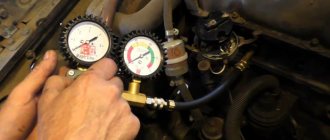
In in-line pumps, a momentoscope is installed on the first section, and in V-shaped pumps of the 33 series - on the eighth section - a glass tube connected through a rubber pipe to a high-pressure fuel line (see figure). The rack is set to the nominal feed position and by manually rotating the pump shaft (by the injection advance clutch), the momentoscope tube is filled with fuel. By turning the shaft back and then slowly rotating it forward, determine the moment when the fuel surface (meniscus) in the momentoscope tube shakes. The rotation is stopped. In this case, the dial of the stand will show the angle to the axis of symmetry of the plunger drive cam. This angle must be within the specifications for that particular pump. So, for the eighth section of a series 33 pump (KAMAZ), this angle should be 42...43˚, and for the first section of 4UTNM pumps - 56˚.
After checking the first (or eighth) section, the torque scope is installed on the remaining sections according to the order of operation of the engine cylinders. The deviation of the injection advance angles by sections should not exceed 20′.
In order to adjust the advance angle of the start of flow in series 33 pumps (KAMAZ), the pusher heel is replaced, which is produced in 18 repair sizes. In pumps such as UTNM, TN, YAZDA, the plunger pusher screw is moved for these purposes. After adjusting the section, this screw is locked with a lock nut.
***
Academic disciplines
- Engineering graphics
- MDK.01.01. "Car design"
- General structure of the car
- car engine
- Car transmission
- Steering
- Brake system
- Suspension
- Wheels
- Body
- Car electrical equipment
- Basic car theory
- Basics of technical diagnostics
- Fundamentals of hydraulics and heat engineering
- Metrology and standardization
- Agreecultural machines. Agreecultural equipment
- Basics of agronomy
- Transportation of dangerous goods
- Materials Science
- Management
- Technical mechanics
- Tips for graduate student
Olympics and tests
- "Engineering graphics"
- "Technical Mechanics"
- "Engine and its systems"
- "Car chassis"
- "Car electrical equipment"
Checking and setting the fuel injection advance angle of the Ural car
To check or set the fuel injection advance angle correctly, you need to know:
- the engine’s crankshaft position during the compression stroke in the first cylinder;
— for the high-pressure fuel pump, the position of the cam shaft is at the beginning of the fuel supply by the eighth section.
In order to quickly and accurately identify and install the engine crankshaft and the camshaft of the high-pressure fuel pump into the specified positions, marks are applied to the fuel pump housing, the automatic fuel injection advance clutch and the rear flange of the drive coupling half.
In Fig. 2 these marks are respectively designated “A”, “B” and “C”.
The fuel injection advance angle is set correctly if the marks “A” and “B” on the fuel pump body and the fuel injection advance coupling are aligned, and the mark “C” on the rear flange of the drive half is in the upper position, to set the rear flange 8 to the position When the “C” mark takes the upper position along the clamp, it is necessary to unscrew the bolts and remove the cover of the lower hatch of the clutch housing.
Inserting a crowbar into the holes in the flywheel, turn the crankshaft to a position in which the “C” mark moves from bottom to top.
At this moment, turn the flywheel lock pin 90˚ and lower it into the deep groove.
Continue rotating the crankshaft using a crowbar at the flywheel until the locking mechanism fits into the hole in the flywheel.
This will be the upper fixed position of the “ C ” mark on flange 8; in this case, the compression stroke will end in the first cylinder.
Align the marks “A” and “B” on the pump housing and the fuel injection advance clutch, install the pump and bolt it to the engine block.
Tighten the bolts securing the pump to the block evenly, in several steps, in the sequence shown in Fig. 3.
Without disturbing the mutual alignment of the marks “ A ” and “ B ” on the pump body and the fuel injection advance coupling, connect the upper end of the driven coupling half 2 with the front plate 4 with bolts 6 (see Fig. 2).
Install the locking pin into the shallow groove, turn the crankshaft one turn, install and tighten the second bolt 6.
When a compressor and power steering pump are installed on the engine, flange 8 (especially the mark on the flange) is difficult to see.
In this case, it is more convenient to determine the upper position of the “ C ” mark on the rear flange 8 of the drive half of the coupling using the valves.
To do this, remove the head cover of the first cylinder (Fig. 4), and turn the crankshaft using a crowbar by the flywheel until the suction valve begins to close (the front valve from the fan).
Move the retainer pin into the deep groove and continue rotating the crankshaft until the retainer enters the hole in the flywheel.
This will be the fixed position of the crankshaft, at which the “ C ” mark of flange 8 (see Fig. 2) will be in the upper position.
After installing the pump on the engine, connecting the control drive, oil supply (discharge) pipes, fuel lines and high-pressure pipes to it, additionally check and clarify the setting of the fuel injection advance angle.
To do this, move lever 2 (see figure) for controlling the regulator to the middle operating position and lower it all the way into bolt 3.
Bleed the engine power supply system with a manual booster pump for 2-3 minutes.
Turn the crankshaft half a turn counterclockwise, as viewed from the fan side, and move the lock pin into the deep groove.
Slowly rotate the crankshaft as it rotates until the retainer fits into the hole in the flywheel.
If the marks on the pump housing and the injection advance clutch are aligned, then the injection advance angle is set correctly.
If the marks are not aligned, then loosen the upper bolt 6 (see Fig. 2) of the driven coupling half, install the lock pin in the shallow groove, turn the crankshaft one revolution in the direction of rotation and loosen the second bolt 6.
Turn the injection advance clutch against the stroke (counterclockwise when viewed from the flywheel) until the bolts stop in the groove of the front plate 4.
Lower the flywheel lock into the deep groove and turn the crankshaft in the direction of rotation until the lock aligns with the hole in the flywheel.
Turn the injection advance clutch by the flange of the driven coupling half 2 in the direction of rotation until the marks on the pump housing and the advance clutch align.
Tighten the upper bolt 6, move the flywheel lock pin into the shallow groove, turn the crankshaft one turn and tighten the second bolt 6.
Check the accuracy of the alignment of the marks on the pump body and the injection advance clutch again using the same method.
After installing and checking the fuel injection timing, start the engine, warm it up to a coolant temperature of 80˚ C and use bolt 3 (see figure) to adjust the minimum crankshaft speed, which should not exceed 600 rpm.