Operating principle of the rear axle
The rear axle is used to transmit torque in a car from the engine, through the gearbox, through a cardan transmission to the rear axle, final drive, differential, axle shafts to the driving wheels of the car.
These components and parts are located in the rear axle of the car, which consists, respectively, of two main parts: a hollow beam (includes two stamped casings welded together) and a housing, a rear axle gearbox.
The rear axles of VAZ 2101-2107 cars have almost the same design and can be said to be unified among themselves. The exception is rear axles in all-wheel drive vehicles and front-wheel drive VAZ vehicles (and their modifications).
Two-stage final drive
When the gear ratio causes excessive dimensions of the driven gear in a single-stage gearbox, a two-stage main gear is used. It allows you to obtain large gear ratios necessary to create significant traction force on the drive wheels. The latter circumstance is becoming increasingly important every year, as it contributes to achieving better acceleration dynamics for road trains and increasing their average speed on the highway.
When distributing the total gear ratio of two-stage gears over individual gear pairs, they are guided by the following provisions:
1 – the gear ratio of the gear that supplies torque directly to the wheels should be maximum;
2 – the gear ratio of a bevel or hypoid stage should be as small as possible. Based on this, trucks increasingly use a second stage in the form of a planetary gear set located in the wheel hub (spaced main gear).
According to the design scheme, two-stage gears are divided into two main groups: gears located in the middle part of the axle (enclosed in one housing) and spaced gears (a single-stage main gear is located in the axle housing and the associated wheel drive or wheel reducer is located separately).
Wheel drives are found only on four-wheel drive trucks. The use of a wheel reducer leads to an increase in the number of parts of the drive axle, but does not increase its weight. This happens because the main parts of the drive axle (main gear, differential, axle shafts) perceive smaller torques, which are increased to the required extent only in wheel gearboxes. Thanks to this, the main parts of the drive axle are smaller in size and therefore lighter in weight than if the same torque were obtained using a single-stage final drive.
Two-stage diversity transmissions come in two types:
– a single-stage bevel or hypoid gear in the axle housing, connected to a cylindrical external gear drive of the wheel drive, which can be located in a separate housing between the differential and the wheel hub or even in the wheel hub. The internal gear transmission is usually located in the wheel hubs;
– a single-stage bevel or hypoid main gear connected to a planetary gear located in the wheel hubs. This design has a number of advantages: small dimensions of the bevel or hypoid gear; the planetary gear is located outside the brakes; coaxial position of gears transmitting torque; division of transmitted torque between three or five satellites; high efficiency, etc.
2121_15.gif
As mentioned above, the rear axle beam of VAZ cars includes two stamped casings welded together in the longitudinal direction. Steel flanges are welded at both ends of these casings; they have machined slots for axle bearings and oil seals, which serve to prevent transmission oil from leaking from the rear axle.
At the ends of the flanges there are four through holes for placing bolts that secure the brake shield, on which parts of the rear wheel brake system are attached: brake cylinders, brake pads.
Using the mentioned bolts and nuts, together with the brake shield, an oil deflector and a special plate are attached to the ends of the rear axle flanges, which secures the axle bearing in the flange seat.
In turn, the oil deflector and the plate are connected to each other with screws through a sealing gasket. The axle shaft with its inner end fits into the spline hole of the axle gear, and with its outer end it is fixed to a ball bearing, which is secured to the axle shaft with a locking ring.
A brake drum is mounted on the outer end of the axle shaft, which has threaded holes for the rear wheel bolts. Steel support cups are welded at the ends of the rear axle beam; the rear suspension springs and shock absorber mounts of the vehicle rest on them.
In the middle part, the rear axle beam diverges and has an opening on the front side, to which the rear axle gearbox housing is bolted.
A stamped cover is welded on the back side of the beam; it contains an oil filler hole, closed with a conical plug. Axle shaft guides are welded inside the beam, which greatly facilitate the installation of axle shafts when assembling the rear axle.
At the bottom of the beam there is an oil drain hole into which a magnetic plug is screwed.
content .. 51 52 55 ..42.
Purpose and design features of driving, steered, combined, supporting bridges.
Purpose and types.
Car axles are metal beams with wheels. Axles are used to install wheels and support the vehicle's supporting system (frame, body). Various types of bridges are used on cars (Fig. 4.39).
Rice. 4.39. Types of automobile axles classified according to different
signs
Rice. 4.40. Types of drive axles classified according to various characteristics
The bridge is called the leader
with drive wheels to which engine torque is supplied. On cars, drive axles can be only the front, only the rear, middle and rear, or all axles at the same time.
Various types of drive axles are used on cars (Fig. 4.40). The most widespread are rear drive axles on limited-terrain vehicles with a 4×2 wheel arrangement, intended for use on paved roads and dry dirt roads.
General arrangement of drive axles.
It is a rigid hollow beam, at the ends of which the hubs of the drive wheels are mounted on bearings, and the main gear, differential and axle shafts are located inside.
Split drive axle housing
(Fig. 4.41, a) Both parts of the crankcase have necks in which steel tubular casings of 1 axle shafts are pressed and secured. Supporting platforms 4 for springs and flanges 5 for fastening the support disks of wheel brake mechanisms are welded to them. Split drive axles are used on passenger cars, light and medium-duty trucks.
Rice. 4.41. Drive axles: a - detachable; b, c - one-piece; 1 - casing; 2, 3 — parts of the crankcase; 4—platform; 5, 6, 12 - flanges; 7 - cup; 8, 10 – CZK –
mattes; 9, 13 - beams; 11 - pipe
42.1. Design of drive axles for cars and trucks
The rear drive axle of a VAZ passenger car (Fig. 4.50) is made in the form of a solid beam 7 with a developed central part of a ring shape. The bridge beam is welded from two stamped steel halves. On one side, a cover 12 is welded to the middle part of the bridge beam, in which there is an oil filler hole with a threaded plug, and on the other side, the housing 16 of the main gear and differential is bolted.
Forged steel flanges 4 are welded at both ends of the beam for attaching brake shields 28 brake mechanisms. Support cups 6 of rear suspension springs and brackets 8 and 26 for fastening suspension parts are also welded to the rear axle beam.
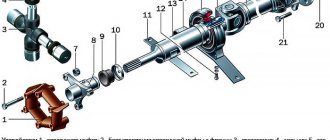
Rice. 4.50. Rear drive axle of VAZ passenger cars: a - general view; b, c - diagrams of the main gear and differential; 1 — brake drum; 2, 17 — rings; 3, 11, 19 — bearings; 4, 21 - flanges; 5, 20 — cuffs; 6 - cup; 7 - beam; 8, 26 — brackets; 9 — axle shaft; 10, 31 - nuts; 12 - cover; 13 — satellite; 14, 15, 22 — gears; 16 - crankcase; 18 — bushing; 23 - axis; 24— washer; 25— body; 27— plate; 28— shield; 29— bolt; 30 - cap; 32 - window
Transmission oil is poured into the rear axle. The internal cavity of the bridge communicates with the atmosphere through a breather, which eliminates the increase in pressure inside the bridge and prevents water from entering when overcoming water barriers. The drive gear 22, made together with the shaft on which the flange 21 is fixed, is installed in the crankcase 16 on two tapered roller bearings 19, sealed by a cuff 20. Between the bearings there is a spacer sleeve 18, which ensures correct tightening of the bearings. The driven gear 14 is bolted to the differential housing 25.
The car uses a small bevel differential, symmetrical, two-satellite, low friction. It distributes torque equally between the driving wheels of the car. The differential housing 25 is installed in bearings 11. The tightening of the bearings and the engagement of the teeth of the drive 22 and driven 14 gears of the main gear are adjusted by adjusting nuts 10. An axis 23 with two satellites 13 is fixed inside the differential housing.
The satellites are in constant mesh with the gears 15 of the axle shafts, which are connected to the splined ends of the axle shafts 9 and have support washers 24.
All differential gears are spur-cut. The vehicle uses semi-balanced axle shafts. The outer end of the axle shaft is mounted in a bearing 3, which is located in the flange 4 of the bridge beam and sealed with a collar 5. The brake drum 1 is attached to the axle flange with bolts 29 and nuts 31 of the wheel and tire, as well as a decorative cap 30. The axle shaft is held from displacement by a special plate 27, fixing bearing 3. The plate together with the brake shield 28 is attached to the flange 4 of the bridge beam.
Rear drive axle of KamAZ trucks
(Fig. 4.51) has a steel welded beam 9, to which are welded a flange for attaching the housing 8 of the main gear and differential, flanges for attaching brake calipers, wheel hub axles, reaction rod mounting brackets and suspension spring supports.
Rice. 4.51. Rear drive axle of KamAZ trucks: 1 - washer; 2, 15 - nuts; 3 - hub; 4 — breather; 5 - drive shaft; 6, 7, 12 — gears; 8 — crankcase; 9 - beam; 10 — satellite; 11 — cross; 13 — body; 14 - axle shaft
main gear
- double, central. The transmission consists of a pair of bevel gears with spiral teeth and a pair of spur gears with helical teeth. The driving bevel gear of the main gear is mounted on the splines of the drive shaft 5, and the driven bevel gear 6 is mounted on the shaft of the drive cylindrical gear 7, which is made integral with the shaft mounted on three roller bearings. The driven spur gear is connected to the differential housing 13, which is installed in the main gear housing on two tapered roller bearings.
Differential
– conical, symmetrical, low friction, four-satellite. The differential housing is split, it consists of two halves. Inside the differential housing there is a crosspiece 11 with four satellites 10 and side gears 12 mounted on the splines of the axle shafts 14.
Half shafts
— flanged, unloaded. Each axle shaft is attached by a flange to the hub 3 of the car wheel, which is mounted on the tip of the bridge beam on two tapered roller bearings secured with a nut 15, a lock washer 1 and a lock nut 2. The wheel hub is sealed with cuffs.
Middle drive axle
KamAZ trucks have a design similar to the rear drive axle. The difference is the presence in the middle drive axle of a lockable center differential, the housing of which is attached to the housing of the final drive of the axle.
Rear drive axle of MAZ trucks
(Fig. 4.52) includes a cast steel beam, double final drive, bevel differential and wafer axle shafts.
Rice. 4.52. Rear drive axle of MAZ trucks: a - longitudinal section; b - gearbox; c - kinematic diagram; 1 - cover; 2, 15 - cups; 3, 6, 11, 13 — gears; 4 — satellite; 5 - axis; 7 — hub; 8 - pipe;
9 — axle shaft; 10 - crankcase; 12 — body; 14 - beam
The main transmission and differential housing 10 are attached to the central part of the bridge beam 14. Thick-walled steel pipes 8 are pressed into the semi-axial sleeves of the bridge beam, on which the hubs of the driving wheels of the car are mounted on two roller bearings.
Double main gear - spaced. It consists of a central and wheel gears. The central gear is made in the form of a pair of bevel gears with spiral teeth and, together with the differential, is placed in a cast housing 10. The driving bevel gear 11 with a shaft is mounted on three roller bearings, and the driven bevel gear 13 is attached to the differential housing 12.
Differential - conical, symmetrical, low friction, four-satellite. The wheel drive is planetary, it consists of a drive (sun) gear 3, three satellites 4, outer 2 and inner 15 cups and a driven (ring) gear 6.
All wheel drive gears are cylindrical, spur-cut. The sun gear and pinions have external teeth, while the ring gear has internal teeth. The sun gear is mounted on the splines of the axle shaft, and the satellites are mounted on roller bearings on axles 5, mounted in the outer and inner cups of the wheel drive, which are bolted and rigidly connected to the bridge beam. The ring gear and cover 1 are attached to the hub 7 of the car wheel.
Torque is transmitted from the axle shaft to the wheel hub through the sun gear, satellites and ring gear. Cover 1, ring gear 6 and wheel hub 1 form a rotating crankcase into which oil is poured to lubricate the transmission gears and wheel hub bearings.
Combined bridge.
This is a bridge that performs the functions of a leading and controlled axle at the same time. The combined axle (Fig. 4.53, a) includes the main gear, differential and drive of the driven steering wheels. Main gear 1 and differential 2 have the same design as the main gear and differential of the rear drive axle.
Rice. 4.53. Schemes of the combined axle (a) and drive (b—d) of the driving steered wheels: 1—main gear; 2 — differential; 3, 5 — axle shafts;
4, 7 — cardan joints; 6 - hub
The drive of the driving steered wheels is a cardan transmission with cardan joints of 4 equal angular speeds. The design of the drive of the driving steered wheels depends on the type of their suspension.
For trucks with dependent wheel suspension (Fig. 4.53, b) and a continuous beam of the drive axle, cardan transmissions with one universal joint with 4 equal angular velocities are used to drive the wheels. The torque to the cardan joint 4 is supplied from the differential 2 by the inner axle shaft 3. The outer axle shaft 5 has a flange from which the torque is transmitted to the wheel hub 6. The hub is mounted on a pivot pin on two bearings, and axle shafts 3 and 5 transmit only torque.
In passenger cars with independent suspension of the drive steered wheels (Fig. 4.53, c), cardan drives with two joints of 4 equal angular velocities are usually used. In this case, the internal hinges provide vertical movement of the wheels, and the external hinges provide their rotation.
With independent wheel suspension, cardan drives are sometimes used with two universal joints of 7 unequal angular velocities and one universal joint of unequal angular velocities (Fig. 4.53, d).
Design of combined bridges.
Let's consider the design of the front axle and wheel drive of VAZ
off-road
(Fig. 4.54).
Rice. 4.54. Front drive axle of VAZ off-road vehicles: 1, 2, 9 - covers; 3 — hairpin; 4 - crankcase; 5 — breather; 6 — bracket; 7 — differential; 8 — main gear; 10, 11 — plugs; 12—under—
rose; 13 - hinge
The front axle is combined. It performs the functions of a driving and steered axle simultaneously and has a permanent drive from the transfer case. The front axle of a car includes a crankcase, final drive, differential and front wheel drive. The front axle housing 4 is made in the form of an integral body with a developed middle part. Covers 9 and 2 are attached to the middle part of the body. Cover 9 is cast from aluminum alloy, and cover 2 is stamped from sheet steel. The cover 9 has a drain hole with a threaded plug 10. On the sides of the housing there are special flanges for installing the bearing covers 1 12 of the internal hinge housings 13 of the front wheel drive. Inside the front axle housing there is a main gear 8 and a differential 7. The front axle housing is attached to the engine brackets using two studs 3 and a bracket 6.
The main gear and differential of the front axle have the same structure as that of the rear axle, and their parts are unified (see Fig. 4.50). The front wheel drive transmits torque from the differential to the front steered wheels. The front wheel drive (Fig. 4.55) is a cardan transmission, which includes a shaft, external and internal joints.
Rice. 4.55. Front wheel drive of VAZ all-terrain vehicles: 1, 11 - housing; 2, 8 — rings; 3 — clip; 4 - ball; 5 - clamp;
6 - casing; 7 - separator; 9 — cover; 10 - shaft
The drive shaft 10 is made solid. The ends of the shaft have splines for installing external and internal drive hinges. The outer joint of the front wheel drive consists of a housing 1, a cage 3, six balls 4 and a separator 7. Inside the hinge body and outside its cage there are special grooves in which the balls are placed. The balls provide a movable connection between the body and the hinge cage. The hinge cage 3 is fixedly fixed on the splined end of the shaft 10 with retaining rings 2 and thrust rings 8.
The outer joint housing 1 has a splined tip, with which it is connected to the front wheel hub of the car. The inner joint of the front wheel drive has a device similar to the outer joint. However, it is somewhat different from the outer hinge in its design.
The housing 11 of the internal joint also has a splined tip, with which it is connected to the side gear of the differential of the front axle of the car. The design of the front wheel drive joints allows torque to be transmitted at significant angles between the shafts, the maximum values of which are 42° for the outer joint and 18° for the inner one.
When assembling the hinges, a special lubricant is added in the amount of 75 cm3 to the outer hinge and 150 cm3 to the inner one. During vehicle operation, the hinges do not require additional lubrication.
Design of the front drive axle of ZIL off-road trucks.
In Fig. Figure 4.56 shows the design of the front drive axle of ZIL off-road trucks. The main transmission of the bridge is double, central. It consists of two pairs of gears: bevel 11 with spiral teeth and cylindrical 8 with oblique teeth. Differential 9 - conical, symmetrical, low friction, four-satellite.
The main gear and differential are located in a housing 10, which is attached to the central part of the bridge beam 12. Ball bearings 15 for rotary axles 1 are attached to the ends of the bridge beam.
Rice. 4.56. Front drive axle of ZIL off-road trucks: 1 - axle; 2, 13 — axle shafts; 3 - flange; 4, 7 — bearings; 5 - hub; 6 — spike; 8, 11 — gears; 9 — differential; 10 - crankcase; 12 - beam;
14—universal joint; 15 — support
Inside each rotary axle there is an outer axle shaft 2, which is connected to the inner axle shaft 13 with a ball joint 14 of equal angular velocities. A flange 3 is installed on the splines of the outer axle shaft for attaching to the hub 5 of the drive steered wheel. The pin for turning the wheel is made split and consists of two spikes 6, which are rigidly fixed in the ball joint. A pivot pin is mounted on the kingpin on tapered roller bearings 7, and on it, also on tapered roller bearings 4, is the wheel hub, which has a tire with adjustable pressure.
content .. 51 52 55 ..
Design and principle of operation
main gear
The main gear can be single or double. The single gear transmits torque to the wheels of the car using one gear pair, and the double gear – using two. Single gear, in turn, can be:
For a cylindrical main gear, the gears are located in the same plane, while for a bevel gear, they are perpendicular to each other. The advantages and disadvantages of the main modifications to single final drives are listed in the following table.
Modifications of single final drives:
The double main gear can be central or spaced. The central one has a simpler design, a large gear ratio and a greater load on all elements of the system. The spaced one has a more complex design, it is more efficient in operation and compact.
Differential
The cross-axle differential distributes torque between different axle shafts. If the car is slipping or slipping, the differential helps it cope with this problem by allowing the wheels to rotate at different speeds.
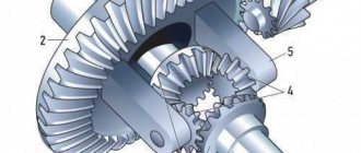
The cup (3) contains the satellite gears (4) and half gears (5). The cup is connected to the driven gear (2). The gear, in turn, receives torque from the main gear drive gear (1). The cup, with the help of satellites, transmits rotation to the axle shafts that drive the driving wheels of the car. The operation of the satellites provides different angular velocities. The amount of torque is unchanged.
A similar device is implemented in most rear-wheel drive cars, such as VAZ-2106, VAZ-2107, Gazelle. It has proven its reliability during operation in the most difficult conditions.
Malfunctions
Causes of malfunctions
The rear axle gearbox is a complex mechanism consisting of a large number of elements. Failure of any one of them can lead to failure of the entire system.
- System overload. One of the most common reasons for failure of the rear axle gearbox is the frequent excess of the required load on the vehicle. For example, when towing heavy vehicles or other loads. During towing, the load on all elements of the system increases significantly.
- Play in crosspieces. Many motorists note that after 5-6 years of using the car, play appears in the crosspieces. This occurs due to increased engine detonation, unregulated ignition and the resulting shocks and shocks. Therefore, during repairs, they carry out diagnostics of all elements of the chassis and do not limit themselves to replacing the transmission mechanism.
- Lack of lubrication. If there is no oil in the rear axle gearbox, it may jam due to overheating. Steel parts may burst or teeth on gears may break. To avoid such problems, it is necessary to keep the lubricant level under control.
- Production of bearings located in “stockings”. This malfunction appears after many years of using the car. It can cause bending of shafts and destruction of gears. As a result, the rear axle gearbox will not be suitable for repair.
Signs of trouble
You will recognize problems associated with the operation of the rear axle gearbox by the characteristic noise:
- Increased bridge noise. The beam may be deformed, the gears and axle shafts may be worn out, the oil level may be low, or there may be a leak. Noise that appears immediately after repair is a consequence of incorrect adjustment.
- Noise during acceleration. If noise appears when the car accelerates, it means the differential or axle bearings are worn out or damaged. Another possible reason is a lack of lubrication in the gearbox.
- Noise during acceleration and braking. If noise appears not only during acceleration, but also when braking the car, it means that the drive gear bearings are worn out or damaged. It is possible that the clearances in the final drive gears are incorrect.
- Noise when cornering. If you notice noise when turning, it means that the axle bearings in the car are faulty. Possible reasons are scoring on the surface of the satellites or their rotation being too tight.
- Knocks when starting to move. Most likely, the gap between the splined connection of the drive gear shaft and the flange has increased. It is also likely that the pinion pin hole located in the differential is worn out.
Vehicle testing
Test 1. Start driving on the highway at 20 km/h, then gradually increase the speed to 90 km/h. At the same time, listen to the sounds the car makes at different speeds. Release the throttle pedal and, without braking, reduce engine speed. Watch for changes in noise.
Test 2: While driving at 100 km/h, shift the lever to neutral, turn off the ignition and roll freely until it comes to a complete stop. Watch the noise change at different deceleration rates.
Test 3. The car is stationary, with the hand brake on. Start the car engine and, gradually increasing the speed, listen to the noise that arises. If you hear the same noise as during test No. 1, then the source is not the gearbox, but other components of the car.
Test 4. If the noise detected in test No. 1 was not repeated in tests No. 2 and No. 3, then it comes from the gearbox. To finally verify this, lift the rear wheels of the car, start the engine and shift into fourth gear. This will allow you to make sure that the source of the noise is the gearbox, and not the suspension or body.
How to avoid premature failure of the axle gearbox? You need to monitor the oil level, listen to noises and knocks in the car, visually inspect the bridge for leaks and external damage to the beam.
Signs of a malfunction of the rear axle gearbox of the VAZ 2107
The gearbox is a fairly expensive part, and its repair is a labor-intensive and complex process. Therefore, you should first make sure that the cause of the noise is a gearbox malfunction. You can do this as follows:
- Choose a flat section of the road and gradually accelerate on it from 20 to 90 km/h. While driving, you should listen carefully and note the appearance and disappearance of extraneous noise from the rear axle gearbox.
- Release the gas and start braking with the engine. While the speed is decreasing, you should also note the moments when noises appear and disappear.
- Accelerate the car to approximately 100 km/h and, switching to neutral, turn off the engine. While the car is coasting, note the presence and disappearance of noise.
To verify the presence or absence of a mono problem like this:
- Park the car, securing it with wheel chocks.
- Raise it with a jack, hanging the rear axle.
- Start the engine, turn on the speed and add gas so that the wheels rotate without load, and the speedometer shows the same speed as during tests on the move.
If the noise remains the same when operating without load as under load, the problem is not in the gearbox. Other rear-wheel drive components should be checked.
If the gearbox does not make noise without load, you will have to start restoring it. Worn gears begin to make noise only under load.
Removing and installing the gearbox
Removing the gearbox
To remove the gearbox, follow these steps:
- drain the oil from the bridge beam;
- lift the rear of the car and place it on stands;
- remove the wheels;
- unscrew the nuts securing the brake shield to the beam;
- slide the axle shafts out of the differential box;
- disconnect the cardan shaft from the gearbox;
- place a stand under the gearbox housing;
- Remove the bolts securing the gearbox to the rear axle beam;
- remove the gearbox from the beam.
Disassembling the gearbox
Attach the gearbox to the stand. Remove the locking plates, differential case bolts and bearing caps, and the roller bearing adjuster nuts and outer races. Before removing the covers, mark them so you can reinstall them later. Remove the differential box with inner rings of bearings and driven gear from the gearbox housing.
To dismantle the drive gear and its parts, you must perform the following steps:
- turn the gearbox housing upside down;
- Unscrew the flange mounting nut with a wrench (2), while holding the drive gear flange (3) with the stopper (1);
- remove the flange;
- remove the drive gear;
- Remove the oil seal, oil deflector, and inner ring of the front bearing from the crankcase;
- press out the outer rings of the rear and front bearings using a mandrel;
- remove the spacer from the drive gear;
- using a puller (1) and a mandrel (4), remove the inner race of the rear roller bearing;
- Remove the inner gear adjusting ring.
- remove the inner rings (2) of the box (3) using a universal puller (1) and a stop (4);
- unscrew the nuts securing the driven gear and knock out the satellite axis from the box;
- we turn the axle gears and satellites, while the latter should roll out into the differential windows so that they can be removed;
- remove the axle shafts with support washers from the gear.
Gearbox installation
To disassemble the gearbox, it is necessary to clean the bridge beam from oil. Then you need to place the sealing gasket on the mating surface, insert the gearbox into the beam and secure it with bolts. First, degrease the holes in the beam and bolts and apply sealant to the bolts. Attach the driveshaft to the gearbox and install the axle shafts and brake drums. Install the wheel, screw in (without tightening) the bolts securing them. Once both wheels are installed, remove the stands and lower the car to the ground. Next, tighten the wheel bolts using a dynamic wrench. Clean the magnetic plug and screw it into the beam. Fill the axle beam with oil through the oil filler hole.
How does a car's rear axle work?
The purpose of the rear drive axle of a car is to change the supplied torque and transmit it at an angle of 90° to the drive wheels. During cornering, this axle allows the drive wheelset to rotate at different speeds.
The bridge also transmits reactive torque and traction forces to the supporting body or frame from the drive wheels and perceives lateral reactions and weight forces while the vehicle is moving when turning.
Design features of a continuous rear axle
An automobile rear drive axle consists of the following elements: differential, rear axle housing, wheel drive axle shafts, final drive. The rear axle housing is designed for mounting the necessary components with their mutually specified location, transmitting torque to the drive wheels.
At the same time, the rear axle housing is one of the components in the suspension of the rear wheel pair. The bridge, through the suspension, absorbs the weight of the vehicle transmitted to the wheels.
The rear drive axle housing is made using the stamping method. The crankcase ends are equipped with welded and pressed forged steel flanges, which are machined after welding. The flanges are distinguished by special sockets for mounting axle bearings, as well as threads for fastening the brake shield.
In the middle area of the axle housing at the front there is a hole for mounting the rear drive axle gearbox, and at the rear this hole is closed with a welded stamped cover. The cover contains an oil filler hole for a screw plug. The lower part of the crankcase is equipped with an oil drain hole; it is also closed with a threaded plug.
Typically, the plug has a magnetic element that collects metal wear debris; they are removed from the plug when changing the oil in the gearbox.
The force supplied to the rear drive axle from the power unit through the cardan drive is increased by the main gear in the gearbox. In addition, the main gear changes the rotation position of the axle by 90° by transmitting torque using differential gears on the axle shaft.
The axle shafts are made of carbon steel and high-frequency hardened along their entire length to increase their strength and provide elasticity. The ends of the axle shafts are equipped with flanges cast together with it, to which wheels and brake mechanisms are attached. The insides of the axle shafts have knurled splines that mesh with the differential gears.
The figure below shows a diagram of the final drive of a vehicle's rear drive axle.
Let's look at the drawing. At the end of the shaft there is a bevel gear, which meshes with another driven gear located on the wheel axis. Thus, the torque “turns” 90°. And due to the fact that the driven gear is larger than the driving gear, the torque immediately increases.
Solid rear axle design
The rear axle of a car includes the following elements: rear axle housing, differential, final drive and wheel drive axle shafts. The rear axle housing is used to install the necessary components with their specified relative positions, transmitting torque to the drive wheels. At the same time, the rear axle housing is also an element of the rear wheel suspension, receiving the weight of the car through the suspension, which is transmitted to the wheels.
The rear axle housing is made by stamping. At the ends of the crankcase, forged steel flanges are pressed and welded, which are finally processed after welding. The flanges have special slots for installing axle bearings and threads for attaching the brake shield.
Rear axle differential
That would seem to be all. We have reached the point where the wheels are starting to spin. But a problem arises when changing the direction of movement of the car by turning left, right or when making a U-turn. If the wheels are placed rigidly on the same axle, then they will always rotate equally. And when turning, say, to the right, the turning radii of the wheels change, and the right wheel travels a shorter distance than the left.
It turns out that one of them must slip. The same effect will occur if one of the wheels is rolled through a hole, and the second on a flat surface. This will lead to increased wear of the wheels, and on a slippery road the car will simply be uncontrollable.
This means we need to make sure that the wheels are independent of each other, but at the same time receive torque. This is the task of the next mechanism - the rear axle differential. The rear axle differential is shown in the figure below.
The drive gear meshes with the driven gear, the appearance of which, as can be seen in the figure, has noticeably changed compared to the previous picture. Inside the driven gear, two bevel gears sit rigidly opposite each other. They are called satellites.
Each satellite is coupled with teeth to two gears on the axle shafts. The axle shafts themselves are not directly connected to each other in any way, only through satellites. That is, at this stage the wheels have gained independence from each other.
Rear axle device
The design of the rear axle of the VAZ 2101 consists of two main elements: a beam and a gearbox. These two nodes are combined into one mechanism, but they perform different functions.
The bridge consists of two main components: a beam and a gearbox
What is a beam
The beam is a structure of two stockings (casings) rigidly connected by welding. Flanges are welded into the ends of each of them, designed to accommodate semi-axial oil seals and bearings. The ends of the flanges have four holes for installing brake shields, oil deflectors and plates that press the bearings.
The middle part of the rear beam has an extension in which the gearbox is located. In front of this extension there is an opening closed by the crankcase.
The rear beam consists of two interconnected hollow stockings
Half shafts
The machine's axle shafts are installed in stockings. At the inner ends of each of them there are splines with which they are connected to the semi-axial gears of the gearbox. Their uniform rotation is ensured by ball bearings. The outer ends are equipped with flanges for mounting the brake drums and rear wheels.
Axle shafts transmit torque from the gearbox to the wheels
Gearbox
The gearbox design consists of a main gear and a differential. The role of the device is to evenly distribute and redirect the force from the driveshaft to the axle shafts.
The gearbox design includes the main gear and differential
main gear
The main transmission mechanism includes two bevel gears: drive and driven. They are equipped with spiral teeth that ensure they are connected at right angles. Such a connection is called hypoid. This design of the main gear can significantly improve the grinding and running-in process of gears. In addition, maximum noiselessness is achieved during gear operation.
The main transmission gears of the VAZ 2101 have a certain number of teeth. The drive has 10, and the driven has 43. The ratio of the number of their teeth determines the gear ratio (43:10 = 4.3).
The main gear consists of drive and driven gears
The driving and driven gears are selected in pairs on special machines in the factory. For this reason, they are also sold in pairs. In case of gearbox repair, replacement of gears is allowed only as a set.
Differential
The center differential is necessary to ensure that the wheels of the vehicle rotate at different speeds depending on the load on them. The rear wheels of a car do not travel the same distance when turning or overcoming obstacles in the form of holes, potholes, or ledges. And if they were rigidly connected to the gearbox, this would lead to constant slippage, causing rapid tire wear, additional stress on transmission parts, and loss of contact with the road surface. The listed problems are solved using a differential. It makes the wheels independent of each other, thereby allowing the car to freely turn or overcome various obstacles.
The differential allows the rear wheels to rotate at different speeds when the car overcomes obstacles
The differential consists of two side gears, two satellite gears, adjusting washers and a cast iron box that acts as a housing. The axle shafts fit into the axle gears with their splines. The latter rest on the internal surfaces of the box using adjusting washers of a certain thickness. They do not contact each other directly, but through satellites that do not have a rigid fixation inside the box. While the car is moving, they move freely around their axis, but are limited by the surface of the driven gear, which prevents the axis of the satellites from moving from the mounting sockets.
The differential housing with the mechanism is installed inside the gearbox on roller bearings pressed onto the housing support journals.
How does a car's rear axle work?
Now let's look at the operating principle of the rear axle differential.
The car drives straight. Torque from the drive gear is transmitted perpendicularly to the driven gear. The driven gear rotates the satellites together with itself. They, due to the gear engagement with the gears of the axle shafts, force them to rotate equally, and the torque goes to both wheels. At the same time, the satellites themselves do not rotate around their own axis.
The car turns. One of the axle shafts with the wheel must rotate at a lower (higher) speed relative to the second. This is what the satellites allow her to do, which, in addition to rotating together with the driven gear of the main gear, begin to rotate around their own axis.
This rotation allows them to transfer the load unevenly, and the wheels rotate at different speeds. Upon completion of the vehicle maneuver, the satellites freeze and rotate only together with the driven gear, which we discussed above. This is the principle of operation of the rear axle differential.
The final element of a car's drive axle is the same axle shafts that are rigidly connected to the wheels.
All mechanisms of the vehicle's drive axle are protected by a metal case with a crankcase containing transmission oil, which serves to reduce friction and cool moving parts.
With a box on the bridge
And now about two-speed transmissions in drive axles. Their use makes it possible to double the number of transmission gears without installing complex multi-stage gearboxes, and lower gear ratios can be obtained by engaging a second gear stage, so that the driveshaft and the first stage do not perceive the increased torque.
Two-speed transmissions are used on long-haul tractors with one drive axle, created on the basis of conventional cars. In this case, a two-speed transmission will allow you to increase the maximum transmission ratio (which is necessary due to the increase in the total weight of the truck) and the number of gears, since the difference between the weights of a loaded and unloaded vehicle (especially in the case of a truck tractor) is very large. In this case, all other mechanisms of the truck remain unchanged.
There are two-speed main gears, including cylindrical external gears rotating on a transverse shaft, and a cam clutch, which, moving along the splines and engaging with the gear rims, rigidly connects them to the shaft. When the clutch moves to the left, a larger gear ratio is engaged, and when moved to the right, a smaller gear ratio is engaged. In main gears of this type, two pairs of teeth always operate, and therefore the gearing losses are the same as in a two-stage main gear, but oil agitation losses increase. The disadvantage of this scheme is the increase in the size and weight of the entire bridge.
On some trucks you can find stepped planetary final drives, mostly two-speed, and more recently three-speed. Planetary gears help to increase the compactness of the unit, but at the same time increase its cost.
Drive axle gearbox
Today there are two types of drive axle gearboxes: wheel and central. The main gearbox of the drive axle (central) is designed to reduce the angular speed of the driven shaft and increase torque.
A wheel-type drive axle gearbox is used to further increase torque while maintaining the basic technical characteristics and dimensions of the central gearbox. Thanks to this, it is possible to increase ground clearance and unify the axles of trucks.
Drive axle gearbox for VAZ cars
The main gear of the drive axle gearbox of VAZ 2101 - 2107 cars and their modernized versions is represented by a pair of bevel gears with an unusual spiral tooth. The type of gearing is hypoid.
The main difference between this type of gearing is that the gearing is crossed at a right angle, while with the standard gearing an intersection is performed. This is done due to the fact that the location of the axis of the drive gears is slightly lower relative to the axis of the driven gear.
Due to this design, in addition to the transverse sliding of the teeth, it was also possible to obtain their longitudinal slipping. Based on this, the process of running in and lapping of gears during operation under load has been improved.
In addition to this, hypoid gearing makes it possible to obtain a maximum overlap coefficient, which maintains ground clearance and ensures quiet transmission, which has a positive effect on the directional stability of the vehicle.
The main gears are formed in pairs, so when performing repair work on the drive axle gearbox and discarding one of all gears, it is necessary to replace them. Gear steaming is carried out in the factory using appropriate equipment.
The principle of selecting a pair of gears for the central gearbox of the drive axle
During selection, the driven and driving gears move along their axes, which causes a violation of the theoretical mounting size. Based on the data obtained, the first amendment is made. Next, measurements are taken of the drive gear head.
The result, which is within the acceptable limits, is the starting point for identifying the second amendment. The amount of corrections, or, in other words, the sum of deviations, is recorded using an electrograph on the plane of the shaft of the drive gear of the main pair and is recorded as a general correction to the theoretical mounting size. These indicators are intended for specialists who repair and assemble the drive axle gearbox.
Gearbox Maintenance
Let's consider the main points of gearbox maintenance.
Radial clearance setting
. Periodic adjustment of the drive axle gearbox makes it possible to prevent tooth wear and also promotes their uniform grinding. Extended radial clearance causes wear on the bearings and teeth of the drive gear shaft and is adjusted using special washers that are placed under the front flanges of the gearbox body. It is characteristic that setting the drive axle gearbox in VAZ vehicles does not differ from the same operation for trucks.
Lubricants
. Adjustment is adjustment, but you must also remember about the working fluid, which is used to lubricate all components of the drive axle gearbox. The most widely used lubricants: domestic - Nigrol or TAD-17, international classification - SAE (72-250) or API (GL-1 - GL-5). The increased viscosity that they are able to maintain at both high and low temperatures allows them to be used to compensate for the high loads that arise during torque conversion.
For the optimal working process of a hypoid gear, it is necessary to maintain the recommended volume of working fluid, since its reduction leads to wear of the teeth of the main pair. But it is also necessary to remember that exceeding the permissible level can cause harm in the situation with VAZ cars by squeezing out the drive axle gearbox seal.
Repair or how not to make a mistake
. Repair of the drive axle gearbox on VAZ cars is carried out in almost any garage cooperative without following the simplest rules for its installation and assembly.
For example, the rear axle gearbox of a Niva car and the front axle gearbox of a Niva car must have the same gear ratios. Violation of this requirement will result in uneven distribution of torque, which can destroy one of the main pairs. There are many cases where would-be repairmen, when repairing the front axle gearbox, made their own modifications.
As a rule, such know-how ends in failure - apart from the failure of the rear and front axle gearboxes, you will not receive anything, and no one will return your money for this “repair”. And if you take, for example, an expensive Mercedes, BMW or Toyota, repairing their rear axle gearboxes will cost you a pretty penny! So, it’s better to turn to professionals and save your money.
Rear gearbox, device and principle of operation
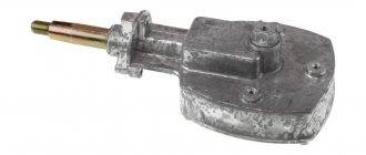
One of the elements involved in transmitting power to the wheels from the engine is the rear axle gearbox, whether it is a gazelle or a VAZ classic, for example 2106, 2107. Although it is characterized by fairly high reliability, it nevertheless requires periodic maintenance and care necessary, like the rest of the machine components. And for this you need to at least understand what it is and what it serves.
Operating principle of the rear axle gearbox
Despite a significant number of car models in which the leading wheel is rear-wheel drive, the gearbox used in the rear axle design always, with rare exceptions, looks almost the same. Here it is worth remembering the definition, according to which a gearbox is a device that changes the rotation speed when transmitting force from one device to another . When the rotation speed changes, its magnitude and direction may change.
It is precisely this principle of operation that is implemented by the gearbox used in the design of the rear axle of almost any vehicle.
Rear axle gearbox design
The design of such a unit must be considered together with other elements included in its composition.
What the gearbox consists of and the principle of its operation is clear from the figure below. It includes:
- final drive (GP);
- cross-axle differential.
The power from the internal combustion engine, or, to be absolutely precise, from the gearbox, goes through drive gear 3 to driven gear 2. This pair of gears is called the main gear, and it changes the magnitude of the torque and the direction of its transmission.
The driven gear is connected to the axle shafts, through which power from the engine is supplied to the wheels. The cross-axle differential allows it to be distributed between different axle shafts, and gives them the opportunity to move at different speeds when changing direction.
A similar construction principle is implemented in many rear-wheel drive cars; VAZ cars, such models as 2106, 2107, Gazelle, are no exception. This device has shown its reliability and ability to work in the most difficult conditions.
Rear axle gearbox: device, types, malfunctions, replacement
1.3 Junior (105) AR 00530
As everyone knows, the classic power unit of a car is the internal combustion engine. Of course, as electric transport spreads, such an engine will become a thing of the past, but this moment is still very far away. In the meantime, all car enthusiasts should understand how the main transport components work. So, here's the engine! To move the car, energy from the engine is taken from the crankshaft. Direct transmission of energy to the drive wheels is impractical - they will rotate too quickly. For this purpose, vehicles are equipped with two devices at once - a gearbox and a special axle reducer. About the features of the latter, malfunctions and maintenance - in the material Avto.pro.
What could the rear axle gearbox be like?
If you look closely at the above figure, you will notice that the drive and driven gears of the GP look somewhat unusual, their teeth are located at an angle, but not straight, relative to each other. This is due to the fact that the so-called hypoid transmission is used. Its peculiarity is the lower load per tooth, quietness and smooth operation. It allows you to increase the reliability of the gearbox used in the design of the rear axle, including those used on VAZ cars, such as models 2106, 2107, Gazelle and other similar cars manufactured using such a mechanism.
However, this is not the only option for implementing a GP, which successfully works as a gearbox in various rear axle designs. Such a device can be made using such gears as:
However, this possibility often remains theoretical or is applied to individual vehicle models. The gearbox, including for the VAZ family of models 2106,2107, as well as other passenger cars, is most often made using a hypoid gear.
