Replacing the front brake pads of a UAZ
Operating a vehicle with a faulty brake system is prohibited for your safety, the safety of passengers and pedestrians. The UAZ is quite a heavy car and the serviceability of the brakes is of great importance. Since the front of the car is heavier, the front wheels are more effective when braking. This article will discuss how to replace the front brake pads of a UAZ.
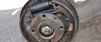
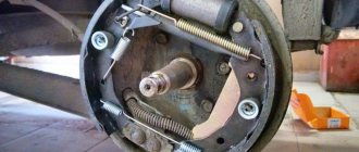
Front brake pads on UAZ drum type
Bleeding brakes UAZ 469
The purpose of carrying out pumping manipulations is to remove the air contained in the internal parts of the braking mechanism. Periodically, once a week, inspect the machine for damage and leaks, paying attention to:
- Presence of mechanical damage to pipes;
- Violation of seals in joints;
- Compliance of the amount of working fluid with the required standard;
- Operation of the foot brake lever.
Braking mechanism UAZ (469, 452):
A sign that it is time to perform pumping manipulations is an increased working stroke of the foot brake lever, as well as detection of dips when pressing the foot brake. In addition, the lubricant is changed after repairs or replacement of components or parts of mechanisms. Regardless of the circumstances, you need to refill DOT-4 brake concentrate and bleed the brakes on UAZ 469 and 452 once every two years.
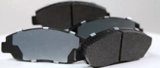
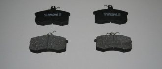
Types of pads
The pads differ in glued and riveted ones. On newer models, disc brakes are installed on the front axle. They are more efficient, but replacement with drum brakes will be discussed here.
In riveted ones, linings made of friction material are attached to the body using rivets, and in the second version they are glued. Drivers still have more confidence in riveted ones. For glued ones, having “ran into” a fake, the lining may come off when heated or wet. Which sometimes leads to wheel jamming and an emergency situation.
The front and rear pads installed at the front have an article and catalog number - 469-3501090, 3151-3501090. The rear one is shorter and has the number 3151-3502091. There are many manufacturers, but I preferred Expert.
Symptoms of a problem
You can determine that the pads need to be replaced without removing the wheels based on several signs:
- when braking, the car pulls to the left or right;
- unpleasant sound of metal rubbing against metal;
- creaking when braking;
- The drum and wheel rim get hot.
Depending on which side the pads are better on, the car pulls in that direction when braking.
Friction against metal is, of course, an extremely bad situation. Pads or linings must be changed when they are worn out, when the rivets are recessed into the lining by less than 0.5 mm and the friction material is damaged.
When the drum with the wheel disc heats up significantly, this may also be due to a faulty pad. For example, the tension spring burst, the lining came off and jammed, but more often it is due to other reasons. An article about such heating is here.
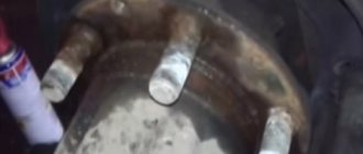
To monitor brake wear, there are holes in the shield.
Front brake pad arrangement
7.1. Service brake system
Symptoms of the problem:
The brake pedal suddenly became soft, but it didn’t just fall right away, but when pressed for the first time it smoothly went down all the way. At the same time, the car smoothly reduces speed. When you press it again, the pedal becomes harder, the car brakes almost normally (taking into account the fact that there are still drums behind), but the pedal slowly reaches the stop.
Inspection of the UAZ:
1. Brake fluid does not leave the reservoir. 2. A visual inspection of the brake lines and hoses did not reveal any leaks. 3. The brake master cylinder is dry. 4. Checking the condition of the front brake pads showed: pad wear is 15-20% 5. Checking the condition of the rear brake pads has not yet been carried out. 6. The patient has a “sorcerer” (from the factory).
Procedures performed:
Today the brake system was bled. All four wheels are bled. One 455 ml bottle of DOT4 brake fluid has been used. Before bleeding, the brake fluid reservoir was at the MAX level. Provided that, according to the Hunter's Primer, there is 0.6 liters of brake fluid in the hydraulic brake system, we can assume that the system is completely bled and there is no air in the system. The treatment didn't help.
It was noticed that when pumping, brake fluid came out of the air release valves of the front brakes under pressure (in a powerful stream) and in a large volume. When bleeding the rear brakes (with the same number of “pumps”), the pressure was weak, the volume of fluid flowing out was less than from the front ones). This may be normal, but it may come in handy for a correct diagnosis.
joint replacement of the vacuum booster and the main brake cylinder.
I found a lot of positive reviews, and even enthusiasm from UAZ drivers, VUT produced by Avtodetal-Service OJSC. This is not advertising! It’s decided - I’m buying VUT and GTZ from ADS. I didn’t even try to look for such a VUT in Kolomna, since the probability is “extremely small” (c) and the price tag will be “horse”. I need to go to the capital... Early on a frosty morning I board the train to Moscow. The carriages are full of people for whom the two and a half hour trip to Nerezinova is just everyday work. Having bought everything I need, I return to the province. So: 42020.3151-3510010 – Vacuum brake booster JSC “ADS” – 2410 rubles.
Vacuum brake booster
3160-3505010 – Main brake cylinder JSC “ADS” – 1240 rub.
Brake master cylinder
3160-3506060 – Front brake hose “Fenox” (there was no ADS) – 340 rub. for two pieces. It's always good to have some in stock.
General view of the purchase
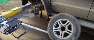
On a clear Saturday afternoon, my friend and I are driving to the garage to work on the brakes.
Let's move on to the repairs:
Still life with old VUT
Leaks on the check valve hose are an accidental spill of brake fluid, and not a defect in the brake system.
Having studied the Primer, we remove the old VUT and GTZ.
The old VUT is twice as heavy as the new one. Why?
Freed up engine compartment space
Using popular advice, the copper lines, after being unscrewed from the GTZ, were covered with protective rubber caps removed from the caliper air release valves. After installing the GTZ, fill the reservoir with brake fluid, press the brake pedal a couple of times until the fluid flows out of the exhaust channels, and only then tighten the copper lines. This allows you to avoid a large air plug at the exit from the GTZ.
New parts in place
There were no difficulties when replacing the VUT and GTZ; unexpected surprises awaited us when bleeding the brakes. Next, using the same “primer book”, with the engine running at idle, we bleed the brake system: rear right, rear left brakes, front circuit of the pressure regulator, front right, front left brakes. So, when we tried to bleed the rear left brake mechanism, we were faced with the fact that the brake fluid was not flowing from the release valve. A careful inspection of the line revealed the cause of the malfunction - a pinched copper tube. In an unpleasant set of circumstances (sagging springs + elements of rough terrain), the bridge stocking “meets” the resonator pipe, and as luck would have it, a copper brake line pipe passes at the point of collision. A blow and the tube is flattened. Since there is no warehouse with spare parts in the garage, and the day is drawing to a close, we decide to carefully fix the problem using impact tools and... tenderness))). The malfunction has been eliminated, but the condition of the tube does not inspire confidence, so this part of the line will subsequently be completely replaced.
copper tube after straightening
Having completed the work, we conduct field tests. After the necessary acceleration, I press the brake pedal with the usual movement... Instead of a leisurely decrease in speed (with Estonian pronunciation and intonation), I get emergency braking with all wheels locked. On the old (working) VUT, this effect was achieved only at the end of the brake pedal stroke. It’s a little unusual, but the result is obvious – the efficiency of the braking system has increased significantly. After just 10 minutes of driving, the behavior of the pedal was mastered - you quickly get used to good things.
Replacing front pads on a UAZ
Before starting replacement work, to comply with safety regulations, put the car on the handbrake and place chocks under the wheels. Further:
- loosen the nuts, jack up the car and unscrew the nuts completely and remove the wheel;
- turning the adjusting eccentric with a key of 17, bring the pads together;
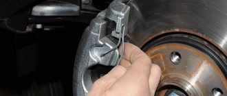
- unscrew and remove the drum;
- remove the pressure springs with cups;
- remove the tension spring;
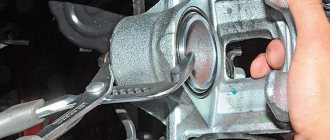
- Using a 19mm wrench, unscrew the support pin nuts and remove them.
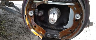
Replacing the front pads of a UAZ
This completes the disassembly, but before replacing, do several operations:
- Check the integrity of the protective caps.
- Place a little grease under the protective cap; this will prevent rust from forming inside the cylinder.
- Grind down the bead on the drum. Check the inner diameter of the drum, its maximum value is 281 mm.
Assembly proceeds in reverse order, but there are several nuances:
- Not everyone has special pliers to install the tension spring. I do it this way: I make a ring with a piece of wire and hook it onto the spring. I pull it out and use pliers to guide it into the seat.
- The support bolt marks work for new pads and drum. In practice, after replacement, you will have to adjust.
- Do not install the wheel until the pad clearances have been adjusted.
After replacement, press the pedal 2-3 times to return the brakes to working condition. Periodically, to maintain the gap between the pads and the drum, it must be adjusted manually.
Removing and disassembling the master cylinder
Removal and disassembly of the main brake cylinder is carried out in the following order:
- Disconnect the lines leading from the master cylinder to the warning device.
- Disconnect the warning device from the brake master cylinder.
- Disconnect the brake master cylinder from the vacuum booster.
- Unscrew the thrust bolt 14 (see Fig. 231).
- Remove the lock ring 22 and take out the thrust washer 21.
- Remove the primary chamber piston assembly 19.
- Unscrew plug 7, remove plug insert 9, return spring 10 and secondary chamber piston assembly 13.
It is not recommended to remove tanks 4 unless necessary. If it is necessary to remove them, unscrew the plugs of the tanks 1, remove the screens 3 and unscrew the fittings 5 securing the tank bodies.
Remove piston assembly 19 only towards the flange, and piston assembly 13 towards the opposite end. Remove the pistons carefully so as not to damage the sealing collars 18 and rings 20. If the pistons cannot be removed freely from the cylinder, first lightly push the piston 13 with the piston 19, and then carefully push the piston 19 by pressing (through the vacated cavity) with a screwdriver or other object onto the spring holder 16 or spring holder screw 17.
Reassemble and install the master cylinder in the reverse order. In this case, install the assembled pistons into the cylinder carefully and only from the side of the corresponding ends of the cylinder. To avoid damaging the seals and rings, do not push the pistons through the entire cylinder cavity.
When assembling piston 19, screw screw 17 until it stops in the piston. Screw the thrust bolt 14 into the crankcase only after installing the assembled piston 19, washer 21 and retaining ring 22.
- thrust bolt 14: 8-10 N*m (0.8-1.0 kgf*m);
- fitting 5: 16-22 N*m (1.6-2.2 kgf*m);
- plugs 7: 167-186 N*m (17-19 kgf*m).
Removing and disassembling the UAZ master brake cylinder:
https://uaz.service-manual.company/rabochaya-tormoznaya-sistema/snyatie-i-razborka-glavnogo-tormoznogo-tsilindra-uaz/
Repair of the main brake cylinder of the UAZ “loaf”
Adjusting the front brakes
For the brakes to be as effective as possible, it is necessary to adjust them so that the lining touches the entire area of the brake drum. To do this, you need to set the gap using both the support bolt and the adjusting eccentric.
I adjust the gaps in the following sequence:
- If you changed the pads, then set the gap without the wheel, it’s more convenient. On the assembled car, jack up the wheel where they need to be adjusted;
- Rotating the drum or wheel with an adjusting eccentric, I bring the part to the drum until braking appears and move it back a little until the wheel moves freely;
- We perform the operation with the second one.
This completes the adjustment; all that remains is to check the heating of the drum. However, it is advisable to repeat it after some mileage after grinding in the brakes.
More precise adjustment is necessary when the drum wears out and a second person is needed.
In this case, we set the eccentric to approximately the middle position, one person presses on the brake with little force. The second one turns the support pin (preferably clockwise) until it turns tightly.
Check the rotation of the wheel; if it turns hard, turn it back a little. If normal, then set the gaps with an eccentric as described above.
Remember, by turning the eccentrics in the direction of wheel rotation, the clearance decreases and, on the contrary, increases when rotating in the opposite direction. This applies to the front pads and the rear pads at the front. The rear pads of the rear axle are reverse adjustable.
Sequence of actions when bleeding the brakes of the UAZ “Loaf”
- The brake fluid identical to that previously filled should be filled into the corresponding reservoir to the required level.
- Cleaning valves that remove air. Removing the protective caps and connecting the hose, the free end of which should be lowered into a container filled with brake fluid.
- Next, you need to sharply press the brake pedal 4-5 times with an interval of 10 seconds , and after each press the pedal should be released smoothly (for these manipulations you will need an assistant). When the pedal is depressed, the bypass valve is turned half a turn with a wrench and the liquid with bubbles begins to fall into the container. After the air plugs come out, the valve screws back. A similar procedure is repeated until the release of bubbles stops and “elasticity” appears in the pedal.
- After all of the above, the bypass valve is closed, the rubber hose is removed, and the cap is attached back to its place.
When bleeding the UAZ brake system, fresh brake fluid should be added to the reservoir, if necessary. The liquid flowing from the hose is not suitable in this form for subsequent use, since it is initially subject to filtration and settling.
It is better to start pumping from the rear right wheel, then move to the rear left, then the front right and, finally, the front left. For cars with split drive, each part will need to be bled separately.
If the bubbles do not disappear after a long pumping, you should recheck the tightness of the entire system, especially the cylinders. Replace or repair if necessary.
Did you like the article? add it to your bookmarks so as not to lose it – PRESS “Ctrl + D”
You can leave a comment or a link to your site. Source
How to Bleed the Master Brake Cylinder / #ProRepair #8
Original
An important advantage of the original front pads is the absence of problems when installing them in their seat. The resource is an order of magnitude greater than its analogues. The only drawback is their cost - it is high compared to analogues.
| Name | vendor code | Name Article Cost, rubles |
| OJSC "UAZ" | 469-3501090-01 0469-00-3501090-01 469-3501090 | From 1 thousand rubles |
Before you start purchasing, it is important to familiarize yourself with all the signs of fakes. Because there are a lot of counterfeits on sale. The cost of analogues is low, but you need to choose carefully.
Substitutes
An important advantage of the UAZ 469 car is the absence of difficulties when purchasing parts. There are many different analogues on the market from different manufacturers. Well-known, world and Chinese. Moreover, not all of them are inferior in quality and durability to the original ones.
| Manufacturer's name | vendor code | Cost, rubles |
| ADS | 469-3502091 42000.046900-3502091-00 | From 200 rubles |
| Alpha | 469-3501090 | From 142 rubles |
| SED-VAD | 469-3501090-1 | From 452 rubles |
It is important to remember that there are several modifications of the UAZ 469 - with the prefix B. The designs of brake systems on the same car model may also differ. Before purchasing, it is important to accurately determine the part number of the front pads.
Original
Buying original parts is always preferable. Their price is slightly higher. But it is not always easy to find UAZ OJSC products in stores. But if possible, it’s worth buying it.
| Name | vendor code | Price |
| OJSC "UAZ" | 469-3501091 | From 290 rubles |
Original parts have standard dimensions, installation is not difficult. Third party products may require filing. Because otherwise it simply does not fit into the standard mounting hole.
Substitutes
Purchasing analogues of original parts is always a certain risk. It is important to read reviews of specific products in advance. And only then buy. Breakage of brake pads on the rear wheels at high speed does not pose such a serious danger as on the front wheels. But it can also cause an accident.
| Name | vendor code | Price |
| Trialli | GF233 | From 1 thousand rubles |
| ADS | 469-3502091 | From 500 rubles |
| TRW | 3151-3502091-10 | From 580 rubles |
Replacing front pads
The process is quite simple. Includes the following main steps:
- Using a large slotted screwdriver, unscrew the 3 screws on which the brake drum is attached;
- the drum itself is carefully removed;
- use a screwdriver or pliers to remove the pad spring;
- the spring cup rotates 90 0 - it is necessary that the slot in the cup aligns with the tip of the pad finger;
- the rod is carefully pulled out of the brake shield;
- using wrench No. 19, unscrew the nut of the block support pin;
Parking brake system of UAZ vehicles
Parking mechanism diagram
Rice. 2 Parking brake system: a – view with brake drum; b – view without brake drum; 1 – adjustment fork; 2 – lock nut; 3 – drive rod; 4 – expansion cracker; 5 – plug; 6 – drive lever; 7 – adjustment screw; 8 – block support; 9 – pusher of the expansion unit; 10 – ball body; 11 – housing of the expansion unit; 12 – brake drum; 13 – first block; 14 – tension spring of pads; 15 – cap; 16 – expansion unit ball; 17 – bolt; 18 – second block; 19 – brake shield; 20 – housing of the adjustment mechanism; 21 – rod; 22 – spring; 23 – spring cup.
Operating principle of the parking mechanism
The brake mechanism of the parking system is equipped on the transfer case and brakes the rear propeller shaft of the Bukhanka. Its design includes a support disk with two pads installed on it, connected by springs. The pads act on the brake drum, which is fixed on the centering belt of the propeller shaft flange. Attached to the top of the support disk is the housing of the expansion unit with pushers, which are attached to the top of the pads. Inside, the pushers are equipped with recesses filled with balls that are located in the rod. The housing of the adjusting element is installed at the bottom of the support disk. The recesses of the housing contain pad supports that can move due to the work of the block and the adjusting screw.
The brake mechanism drive includes a lever mounted on the support disk and an expansion element supporting the rod of the balls. The free end of the lever is attached to the fork, which in turn is attached to the rod using a lock nut. The drive rod is attached to the parking brake lever, which is installed in the driver’s cab.
In addition, on the UAZ Bukhanka, the parking brake system drive is supplemented with an extension located between the parking brake lever and the brake mechanism. This extension cord is a steel cable with elements for its fastening.
Read also:
— Tuning UAZ Bukhanka — making an exclusive out of a simple bus — Tuning UAZ Hunter — a whim or necessary modifications? — How to lift a UAZ “Loaf” — A trunk on a Niva with your own hands — A trailer on a UAZ with your own hands — Are tracks effective for a Niva?
Replacing rear pads
The front pads are replaced when the friction lining is worn by 2 mm or less. Replacement is performed in the following sequence:
- the brake fluid plug is unscrewed;
- then you need to press the brake pedal several times to reduce the vacuum in the brake system;
- the wire of the pad wear sensor is unscrewed;
- unscrew 3 screws holding the brake drum in place;
- using a wooden block and a hammer, the drum is knocked out of its seat;
- the spring holding the pads in place is carefully detached;
New pads are installed on the seat. After the replacement is completed, it is necessary to bleed the brake system. It is necessary to create a vacuum and remove air. To do this you will need to drain some of the liquid. Accordingly, it must subsequently be topped up to the required level. The wheels must be pumped in a certain sequence:
- left front;
- right front;
- left rear;
- right rear.
Before driving, it is important to check that the brake system is working. Sometimes it doesn't make sense to replace the entire pads. You can simply rivet new friction linings onto the old base. But this does not always make sense.
source
Bleeding the brakes, sequence
Before pumping the brakes on your UAZ, look for a dry, flat surface. In addition, you will need an assistant, since it is difficult to perform the operation alone, but in case of urgent need it is possible.
The sequence of the process is as follows:
- We remove valve plaque;
- We check whether there are any smudges or leaks in connections and pipes;
- We control the amount of working fluid in the container for compliance with the standard. If necessary, add “MAX” to the desired mark. We carry out manipulations, constantly check and bring the liquid to the required level; it is impossible for the mixture to drop to the “MIN” mark.
- We pump the foot brake lever without starting the power plant;
- We remove the safety cap from the cylinder bypass valve located at the rear (right) and install a light-transmitting tube, product size 400mm. We wet the unoccupied edge of the tube in a container containing half a liter of working suspension and leave the tube there;
- Press the foot lever until it stops 4-5 times;
- Holding the lever with your foot, unscrew (key 11) the bleeding valve, make ½, ¾ turns;
- We control the movement of air masses in the form of bubbles from the cavity of the tube lowered into the suspension;
- When the stop lever goes all the way down, close the bleeder valve and press out the mechanism;
- We carry out the actions in the required order as long as necessary to completely remove the bubbles;
- We remove the tube and install the safety cap;
- Using the same method, we bleed the stop cylinder located at the rear (left);
- Afterwards, we perform similar actions on the pressure regulator.
The cylinders on the front wheels are pumped in the same way, the sequence of manipulations is: bottom right, top right, bottom left, top left. It is necessary to observe the pumping order. Otherwise, a situation is possible when the brakes on the UAZ loaf are not pumped. If technically there is no wear and tear, then the problem lies in a violation of the procedure.
When the actions taken do not produce results and air is also present in the mechanism, then when force is applied, the stop lever will be elastic to the touch. In this situation, the process is repeated again until a feeling of hard leverage appears.
Air control in brakes:
When the process is completed and the liquid continues to bubble, check the seals of the joints, pipes, and cylinders (main and working). Check threaded connections, change seals, gaskets, rings, and cylinder cuffs. As for replacing working cylinders, the replacement process occurs as a complex.
At the end of the steps, fill the brake fluid to about 0, fix the cap of the container with a meter that monitors the decrease in level. The liquid is changed until the new, light consistency replaces the old, dark matter.
Adjusting the brake pads
Adjust the installation of brake pads in the following order:
- Raise the wheel whose brake mechanism needs to be adjusted with a jack.
- Unscrew the support pin nuts slightly and set the support pins to the initial position (the marks on the ends of the support pins should be located as shown in Fig. 226 and 227).
Fig. 226. Brake mechanism of the front wheel: a-marks on the support pins 1-shield; 2-connecting tube; 3-wheel brake cylinder; 4-bypass valve; 5-way coupling; 6-pin pad spring; 7-pad lining; 8-brake pad; 9-protective cap; 10-piston; 11-O-rings; 12-piston spring; 13-adjusting eccentric; 14-support pad pin; 15-nut; 16-bolt coupling; 17-gaskets; 18-support bushing; 19-bolt adjusting eccentric; 20-puck
Fig. 227.
Rear wheel brake mechanism: a-marks on support pins 1-support pin; 2-shield 3-eccentric; 4-eccentric axis head; 5-wheel brake cylinder; 6-bypass valve; 7.13-brake pads; 8-protective cap; 9-piston; 10-o-rings; 11-piston spring; 12-coupling spring Pressing the pedal with a constant force of 118-147 N (12-15 kgf), turn the support pins so that the ends of the shoes on the finger side rest against the brake drum (Fig. 239).
Rice. 239. Adjusting the rear wheel brake pads using support fingers
Determine the moment of contact of the pads with the drum by the increase in resistance when turning the support pin. In this position, tighten the support pin nuts, being careful not to turn the pins.
- Turn the adjusting eccentrics until the pads touch the brake drum until the wheel brakes.
- After stopping pressing the pedal, turn the adjusting eccentrics in the opposite direction so that the wheels rotate freely, without the drum touching the pads.
When installing new pads with unworn brake drums correctly, the “a” marks on the support pins should be located as shown in Fig. 226 and 227 or with deviations from this position in one direction or the other up to 50 degrees.
When installing new pads, when the friction linings have not yet been run in to the surface of the drums, the brake drums may heat up slightly after the indicated adjustment. After several braking sessions the pads will break in and the heating will stop. If the brake drums become very hot, move the pads slightly away from the brake drum using the adjusting eccentrics.
source
Brake system maintenance and repair
The UAZ-452 brake system includes hydraulic and mechanical elements. The first sign of a malfunction is the “failure” of the clutch pedal - the pressure in the system is below normal.
The cause of the problem may be different:
- air has entered the circuit;
- the integrity and tightness of the pipeline is compromised;
- liquid was not added on time;
- failure of the circuit mechanisms.
How to bleed the brakes
After the brakes have failed, regardless of the work performed, bleeding the UAZ brakes is a necessary action.
Pre-clean the valves on all four wheels from dirt. At the same time, you can check the condition of tubes, hoses and connections for mechanical damage and leaks. To do this, perform the following actions:
- Add brake fluid to the reservoir to about or a little more. The level must be monitored throughout the entire operation, otherwise air will enter the system again.
- For the valves, you need to select a plastic or rubber tube of suitable diameter, the length of which should allow the second end to be lowered into a container with brake fluid. The structure serves as a one-way barrier between the circuit and the atmosphere.
- You can't bleed the brakes alone, you need an assistant. One person sits in the cabin and, upon command, sharply pressing the pedal several times, holds it pressed all the way; the second one under the car at this moment releases the valve using a key at 11 so that the air comes out. When the bubbles stop or the pedal hits the floor, the valve closes. The procedure is repeated on all wheels, starting with the rear right one, until all the air is released from the system and the movement of the lever under the foot becomes natural for a properly operating machine.
How to separate the pads
It is possible that the brakes are pumped, but when you press the lever sharply, the car does not skid, as if there is not enough effort.
If you put the car on jacks and spin the wheel, it should rotate freely. In a situation where it spins tightly and a grinding noise is heard, most likely the pads need to be moved apart. This is done like this:
- On the back of the brake drum you need to find a nut with a screw lock and unscrew it 0.5-1 turn.
- Turn the wheel and tighten the nut until it stops. After this, gradually loosen until the rotation becomes silent and easy.
- Fix the position and repeat the operation on the remaining wheels.
Replacing pads
The friction linings wear out - they become thin, chips and grooves appear on them, so the UAZ brake pads need to be replaced periodically.
After the car wheel is removed, the procedure for replacing the brake pads on the UAZ looks like this:
- unscrew the brake drum;
- Having removed the protective cap, spread the pads and take out the tension spring;
- by pressing and turning 90º, remove the upper cup and remove the pressure spring and its rod;
- take out the support pin, bushing and remove the block.
On some models, the front pads are longer than the rear ones.
How to tighten the handbrake
The UAZ hand brake is adjusted in the following order:
- We hang out the rear wheel of the car.
- Set the gear shift lever to the neutral position.
- We lower the handbrake completely.
- We tighten the adjustment screw so that the drum stops turning freely by hand.
- Let go until the drum begins to rotate slightly, turning the screw ½ turn. We try the lever - there should be 5-7 clicks.
- We go to the drive, unscrew it, and remove the cotter pin.
- We twist the fork, tighten the cable, align it and insert the cotter pin.
Pull the handbrake and try - the car should stand on a slope of 20-30º.
Replacement and repair of the main brake cylinder
Before repairing the GTZ, you need to pump out the liquid from both tanks that are located on it. This can be done with a 20 cc syringe. Using a screwdriver, unscrew the containers and remove them.
Use a 17 wrench to unscrew the pipes, and be sure to hold the nuts on the pipes with a second wrench (12). Do not apply any force, as copper cracks easily.
After this, remove and clean the signaling device. We disconnect the cylinder from the vacuum, remove the lock washer on one side and unscrew the end nut on the other. We take out the insides of the GTZ. Inspect the inner surface for scratches. We change the repair kit and assemble it in the reverse order.
If the performance check shows that the device is easier to replace, then we remove the old one without disassembling it and install the purchased one. Fill in the liquid and bleed the system. Before installation, you can pre-fill the tanks and manually “drive” the piston.
Blog about UAZ
The UAZ-469 and UAZ-469B vehicles have two independently operating braking systems: drum service brakes on all wheels with a hydraulic drive and a parking brake system with a mechanical drive.
Front and rear service brakes of UAZ-469 and UAZ-469B.
The front service brakes have two wheel cylinders, each of which acts separately on the pad. The rear service brakes have one wheel cylinder acting on both pads.
Service brakes of the front wheels of UAZ-469 and UAZ-469B, design and differences.
The service brakes of the front wheels of the UAZ-469 and UAZ-469B differ in shields with different stampings, configuration, cylinders and connecting tubes of the cylinders, as well as the working position of the cylinders.
The brake shield of the UAZ-469 car is attached together with the axle to the cover of the wheel gearbox, and for the UAZ-469B car it is attached directly to the steering knuckle axle. Two wheel cylinders are secured to the shields using support pins and nuts. On the support pins, between the washers under their heads and the support lugs of the wheel cylinders, bronze eccentrics are fixedly mounted, on which the brake pads rotate.
By turning the support pins with eccentrics, you can move the support ends of the pads relative to the brake shield. They adjust the brakes using support pins when assembling them at the factory or when repairing brakes with replacing pads or linings. The friction linings of the pads are attached to the rim with aluminum rivets recessed into the body of the lining.
The moving ends of the brake pads fit into the grooves of the piston tips of the wheel cylinders. The pads, with the inner surface of their rims, rest on adjusting eccentrics, movably mounted on the brake shield. The eccentrics are kept from arbitrary rotation by springs. The pads are pressed against the eccentrics by tension springs.
The hexagonal heads of the adjusting eccentric bolts are located on the outside of the brake shield. Using eccentrics, the required gap is established between the pads and the drum. The pads are kept from lateral displacement by the ends of the adjusting eccentric bolts and springs installed in the middle part of the pads.
Inside each wheel cylinder there is a piston with two rubber O-rings and a spring that presses the wheel cylinder piston to the thrust end of the pad rib.
The wheel cylinder has two holes. One hole serves to supply brake fluid from the drive system, and the other to release air from the system during bleeding; it is closed by bypass valves, which, in the closed position, ensure tightness. To prevent clogging, the valve opening is closed with a protective cap. The internal cavities of the wheel cylinders are protected from moisture, dust and dirt by rubber caps.
Service brakes of the rear wheels of UAZ-469 and UAZ-469B cars, design and differences.
The service brakes of the rear wheels of the UAZ-469 and UAZ-469B differ only in their shields. The rear wheel brake has one wheel cylinder for both pads. The pistons, O-rings and other cylinder parts are the same as the front brake.
In the lower part of the brake shield there are support pins on which are mounted the same as on the front brakes, adjusting bronze eccentrics, against which the pads swing. The rear brake pad lining is shorter than the front brake pad lining. This is designed to ensure that the wear on the rear and front pads is equal.
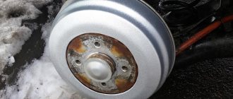
Brake drums.
Same on all wheels. The drums are attached to the hub with three screws, which are unevenly spaced around the circumference, this ensures that the drum is installed on the hub in one specific position, in which the drum assembly with the hub was processed. It is not recommended to move brake drums from one hub to another, as this will increase the runout of the working surfaces of the drum relative to the brake linings.
Hydraulic drive of service brakes UAZ-469 and UAZ-469B.
Consists of a brake pedal, master cylinder, pipelines with connecting fittings and wheel cylinders. In the initial position, the brake pedal is held by a tension spring, which constantly presses it against a rubber stop fixed to the floor of the body. The pedal at its lower end is connected through a pin to the master cylinder pusher fork.
The brake master cylinder body is made in the same casting as the reservoir for the working fluid. At the top of the tank there is a lid with a hole for filling liquid, which is closed with a stopper. The cavity of the master cylinder communicates with the atmosphere through a hole in the plug. Inside the cylinder there is a piston with sealing collars, exhaust and intake valves.
A washer is installed between the piston and the inner cuff. The return spring constantly presses the master cylinder piston with sealing lips against a thrust washer held in place by a retaining ring. The opposite end of the spring presses the intake valve to the seat. The cylinder communicates with the liquid reservoir through two holes. A hole with a diameter of 0.7 mm is compensation; it connects the reservoir with the working cavity of the cylinder. This hole is located in close proximity to the edge of the inner sealing collar.
The second hole with a diameter of 6 mm is a bypass; it connects the reservoir with the non-working cavity of the cylinder, enclosed between the outer and inner sealing collars. The main cylinder on the pusher side is closed with a rubber cap that protects the internal cavity of the cylinder from dust and moisture. The master cylinder is connected to the brake wheel cylinders by a piping system consisting of copper or steel double-layer pipes, flexible hoses, fittings, couplings and tees.
The tightness of the tube connections is ensured by tightly tightening the flared end of the tube onto the conical surface of the tee seat, coupling or fitting. Couplings and fittings are sealed with washers made of soft copper.
Maintenance of service brakes UAZ-469 and UAZ-469B.
The fluid level in the master brake cylinder is systematically checked and, if necessary, brought to normal. The level should be 15-20 mm below the top edge of the filling hole. The connections of the hydraulic brake drive pipelines must be sealed, and the mountings of the tubes on the frame and rear axle must be reliable. Do not operate a vehicle with damaged pipes and hoses.
The brake drums are periodically removed and all parts are cleaned of dust and dirt. The frequency of this operation depends on the operating conditions of the vehicle. In summer and when driving on dirty roads, cleaning should be carried out more often, in winter less often. After removing the drum, the reliability of fastening the wheel cylinders to the shields is checked.
It is necessary to pay attention to the condition of the wheel cylinders, protective caps, the degree of wear of the friction linings, as well as the condition of the brake drum. Pads whose brake linings become oily during operation are dipped in gasoline for 20-30 minutes. Then the working surfaces of the pads are thoroughly cleaned with sandpaper or a wire brush. In case of significant wear, the rivets sink less than 0.5 mm, the linings are replaced.
If there are deep grooves, scuffs or uneven wear on the working surface of the drum, then the drum is bored based on the outer races of the hub bearings. With the hubs removed, the bolts securing the brake shields are tightened.
To ensure trouble-free operation of the brakes, you must regularly flush the system and fill it with fresh brake fluid. It should be borne in mind that in order to thoroughly flush the system, it is necessary to completely disassemble the main and wheel cylinders, and blow out the pipelines. Rubber and metal parts of the cylinders are washed in clean brake fluid. After flushing, it is recommended to lubricate all cylinder parts that come into contact with the brake fluid.
Replacing a UAZ brake cylinder
The safety of any vehicle largely depends on the efficiency and uniformity of braking. The UAZ “Bukhanka” was no exception, the all-wheel drive of which only increases the importance of high-quality formation, strengthening, distribution and transmission of braking forces.
The center of the car's braking system is the main brake cylinder , which is entrusted with the final function of converting the mechanical movement of the pedal into fluid pressure moving along hydraulic lines.
All models of the UAZ-452 series are equipped with two-section master brake cylinders . The part is located on the cover of the vacuum booster; the top is covered by reservoirs with brake fluid, connected to the working sections through bypass and compensation holes.
The liquid located in the tanks is used by the system to replenish small process losses, for example, minor leaks or evaporation. Most often, tanks are made of translucent plastic and equipped with a scale or simple liquid level sensors.
In the longitudinal body of the main brake cylinder there are two pistons communicating with each other. The first piston is connected to the rod of the vacuum booster, the second does not have a rigid connection with mechanical parts.
The tightness of the system and the tight fit of the pistons to the cylinder mirror are ensured by rubber cuffs.
Return springs are installed between the pistons, as well as between the second piston and the rear wall of the crankcase, which are necessary to hold the elements in their original position until the pedal is pressed and return to it after the control action has ceased.
The incoming mechanical force is perceived by the master cylinder rod, equipped with a boot, a retaining ring and an outer collar.
Outgoing hydraulic forces are transmitted through the channels of the first and second circuits to the corresponding lines and are perceived by the working bodies of the wheel cylinders.