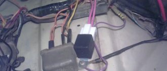
Connection diagram for generator in VAZ cars
The generator in cars is designed to generate electricity and charge the battery. If the normal operation of a car electric generator is disrupted, the battery begins to discharge and soon the car will stop starting completely - there is not enough battery charge. This device consists of a three-phase diode bridge, which, in turn, has 6 silicon diodes. Electrical voltage is created by the excitation of the rectifier at the moment when the rotor poles change under the stator windings. When the rotor rotates inside the machine stator, the poles of the rotor change. To increase the value of magnetic fluxes, the stator contains an electromagnetic exciting winding in the area of the magnetic cores. Marking and designation of wires:
- P - pink.
- F - purple.
- O - orange.
- B&W - black and white.
- KB - brown and white.
- CHG - black and blue.
- K - brown.
- H - black.
- B - white.
Connection diagram for the VAZ-2101 generator
Structurally, generator 2101 consists of the following main elements:
- The rotor is a moving part that rotates from the engine crankshaft. Has an excitation winding.
- The stator is the stationary part of the generator and also has a winding.
- Front and rear covers , inside of which bearings are installed. They have eyelets for attaching to the internal combustion engine. The back cover contains a capacitor necessary to cut off the alternating current component.
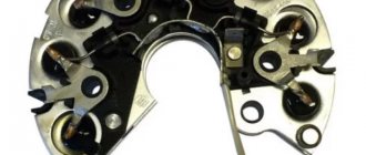
- Semiconductor bridge - called a “horseshoe” for its similarity. Three pairs of semiconductor power diodes are mounted on a horseshoe-shaped base.
- A pulley on which the VAZ-2101 generator belt is placed. The belt is V-shaped (on modern cars a multi-ribbed belt is used).
- The voltage regulator is installed in the engine compartment, away from the generator. But still it must be considered part of the structure.
- The brushes are mounted inside the generator and transmit the supply voltage to the field winding (on the rotor).
Types of relay regulators
Modern relay regulators do not use electromagnetic relays as a base - they are completely semiconductor. The use of semiconductors made the device both reliable and very compact, but reduced its maintainability to almost nothing. There are quite a few types of relay-regulators, but one thing is essential: there are no fundamental differences between relays of different types. It is worth distinguishing two types:
- Built-in . Sometimes this type of relay is called a “chocolate bar”. Located inside the generator and combined with the brush assembly;
- Taken out . Attached to the car body.
Spare parts for Mazda 2
Trunk glass (3/5th rear door (lyada)
1.3 ZJ-VE
Spare parts for chevrolet volt
Front brake caliper repair kit 1.4 A14XFL
The housings of all new regulators are non-separable, so getting to the semiconductor “filling” will not be easy. The body can be either polymer or steel. The weak point of the regulators is rather the contacts and wires. The former oxidize over time, and the insulation of the latter may melt or suffer mechanical damage.
Connection diagram for the VAZ-2107 generator
1 - battery; 2 - negative diode; 3 - additional diode; 4 - generator; 5 - positive diode; 6 - stator winding; 7 - voltage regulator; 8 — rotor winding; 9 — capacitor for suppressing radio interference; 10 — mounting block; 11 — battery charge indicator lamp in the instrument cluster; 12 - voltmeter; 13 — ignition relay; 14 - ignition switch.
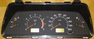
Connection diagram for the VAZ-2108 generator
The VAZ-2108 generator has a rather massive stator winding, since it uses a large cross-section wire. It is with its help that electricity is generated. The wire is wound evenly over the entire inner surface of the stator into recesses specially provided for this purpose in the magnetic core. It’s worth talking about the latter separately. The middle part, the generator stator, consists of a series of thin metal plates pressed tightly together. They are often boiled on the outside to prevent separation.
Connection diagram for the VAZ-2109 generator
- Alternator. The 37.3701 or 94.3701 series can be installed.
- Negative diode.
- Additional diode.
- Positive diode.
- Alternator warning lamp, also known as battery discharge lamp.
- Instrument cluster.
- Voltmeter.
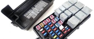
- Relay and fuse box located in the engine compartment in the compartment between the engine and the vehicle interior.
- Additional resistors built into the fuse mounting block.
- Ignition relay.
- Egnition lock.
- Accumulator battery.
- Capacitor.
- Rotor winding.
- The voltage relay is located in the engine compartment.
Connection diagram for the VAZ-2110 generator
On VAZ-2110, 2111 and 2112 cars, a 94.3701 generator was installed with a maximum output current of 80 Amperes and a voltage = 13.2–14.7 Volts.
Here is a breakdown of the connection diagram for the generator on the ten :
- Battery 12V;
- generator 94.3701;
- mounting block;
- egnition lock;
- battery charge indicator lamp in the instrument cluster
Diagnostics of the voltage regulator
You can check it in several ways. Start the engine and let it run until its temperature reaches operating temperature. Turn on the low beam headlights and fog lights (if any). Arm yourself with a multimeter and measure the voltage on the battery. The maximum value should be 14.8 Volts. If you observe an excess of this value, then you need to change the voltage regulator relay. This is the easiest way to diagnose a device.
The one in which you need to remove the regulator from the generator will be a little more complicated. True, for this you need to do very little. Using a Phillips screwdriver, unscrew the two bolts, disconnect the wire and remove the device along with the brush assembly. This way the voltage regulator is removed on VAZ 2108 and similar models. If it is installed in the engine compartment, as in the VAZ 2106, then removing it is much more convenient.
For diagnostics, you will need a regular light bulb designed to operate at 12 Volts. It is desirable that its power be no more than three watts. The regulator has two terminals, designated by the Russian letters “B” and “V”. With their help, the device is powered from a DC source. A light comes on between the contacts that go to the brush mechanism.
If the output of the power source is no more than 14 Volts, then the light should be on. If it rises above 15 Volts, the lamp should go out. If in both cases the light bulb lights up or does not light up at all, then there is destruction of the semiconductor elements. Then only a complete replacement of the regulator will help.
And so the saga with the on-board network continues. Last year I changed my native generator to a 372.3701 55A generator from a VAZ 2108 (I bought it used, www.drive2.ru/l/1322019/), my native one gave, in principle, normal voltage, but when driving at night the light flickered at XX the voltage dropped and everything dimmed, after replacing it with a new generator everything became normal, but the voltage was a little low, it didn’t reach 14 without load, but the battery was charging and there were no problems, but I want perfection!
How to check the generator yourself
How to check a VAZ generator using the example of model 2109. Generator type 94.3701 alternating current, three-phase, with a built-in rectifier unit and an electronic voltage regulator, right-hand rotation.
Generator connection diagram . The voltage to excite the generator when the ignition is turned on is supplied to terminal “D+” of the regulator (terminal “D” of the generator) through indicator lamp 4 located in the instrument cluster. After starting the engine, the excitation winding is powered by three additional diodes installed on the generator rectifier block. The operation of the generator is controlled by a warning lamp in the instrument cluster. When the ignition is turned on, the lamp should be on, and after starting the engine, it should go out if the generator is working. If the lamp is brightly lit or glows half-lit, it indicates a malfunction.
The “minus” of the battery should always be connected to ground, and the “plus” should always be connected to the “B+” terminal of the generator. Failure to turn the battery back on will immediately cause increased current through the generator valves and damage them.
It is not allowed to operate the generator with the battery disconnected. This will cause short-term overvoltages to occur at the “B+” terminal of the generator, which can damage the generator voltage regulator and electronic devices in the vehicle’s on-board network.
It is prohibited to check the functionality of the generator “for spark” even by briefly connecting the “B+” terminal of the generator to ground. In this case, significant current flows through the valves and they are damaged.
Operating principle of the regulator relay
Thanks to built-in resistors and special circuits, the relay is able to compare the amount of voltage generated by the generator. After which, too high a value leads to the relay being turned off, so as not to overcharge the battery and damage electrical appliances connected to the on-board network.
Any malfunctions lead to precisely these consequences: the battery becomes faulty or the operating budget increases sharply.
Summer/winter switch
Regardless of the season and air temperature, the operation of the generator is always stable. As soon as its pulley begins to rotate, electric current is generated by default. However, in winter the insides of the battery freeze, and it replenishes the charge much worse than in summer.
The summer/winter switches are either on the body of the voltage regulator, or the corresponding connectors are marked with this designation, which you need to find and connect the wiring to them depending on the season.
Rice. 19 Voltage regulator with winter and summer terminals
There is nothing unusual in this switch, these are just rough settings of the regulator relay, which allows you to increase the voltage at the battery terminals to 15 V.
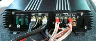
Connection to the generator's on-board network
If, when replacing a generator, you connect a new device yourself, you need to take into account the following nuances:
- First you should check the integrity and reliability of the contact of the wire from the car body to the generator housing
- then you can connect terminal B of the regulator relay with the “+” of the generator
- Instead of “twists” that begin to heat up after 1–2 years of operation, it is better to use soldering of wires
- the factory wire must be replaced with a cable with a minimum cross-section of 6 mm2 if, instead of a standard generator, an electrical appliance rated for a current of more than 60 A is installed
- The ammeter in the generator/battery circuit shows which power source is currently higher in the on-board network
Rice. 20 Connecting a generator using the example of a VAZ
Ammeters are necessary devices with which you can determine the battery charge and the performance of the generator. It is not recommended to remove them from the scheme without special reasons.
This is interesting: Technical characteristics of G4GC 2l/137 – 143 l. With.
Remote controller connection diagrams
An external generator voltage regulator relay is installed only after determining which wire it should be connected to. For example:
- on old RAFs, Gazelles and Bullheads, relays 13.3702 are used in a polymer or steel case with two contacts and two brushes, mounted in a “–” open circuit, the terminals are always marked, “+” is usually taken from the ignition coil (B-VK terminal) , contact Ш of the regulator is connected to the free terminal of the brush assembly
- in “Zhiguli” relay regulators 121.3702 of white and black colors are used, there are double modifications in which, if one device fails, the operation of the second device continues by simply switching to it, mounted in the “+” gap with terminal 15 to the terminal of the ignition coil B-VK, terminal 67 is attached to the brush assembly with a wire
Car enthusiasts call built-in relay regulators “chocolate bars”, labeled Y112. They are mounted in special brush holders, pressed with screws and additionally protected with a cover.
On VAZ cars, relays are usually built into the brush assembly, full marking Y212A11, connected to the ignition switch. If the owner replaces the standard generator on an old domestic VAZ with an AC device from a foreign car or a modern Lada, the connection is made according to a different scheme:
- The car owner decides on the issue of fastening the body independently.
- The analogue of the “plus” terminal here is contact B or B+; it is connected to the on-board network via an ammeter
- Remote relay regulators are usually not used here, but built-in ones are already integrated into the brush assembly, from them comes a single wire marked D or D+, which is connected to the ignition switch (to the coil terminal B-VK)
Rice. 21 Replacing the standard relay with a three-level regulator
For diesel internal combustion engines, generators may have a W terminal, which is connected to the tachometer; it is ignored when installed on a car with a gasoline engine.
Checking the connection
After installing a three-level or other relay regulator, a performance check is necessary:
- the engine starts
- The voltage in the on-board network is controlled at different speeds
After installing the alternator and connecting it according to the above diagram, the owner can expect a “surprise”:
- when the internal combustion engine is turned on, the generator starts, the voltage is measured at medium, high and low speeds
- after turning off the ignition with the key... the engine continues to run
In this case, you can turn off the internal combustion engine either by removing the excitation wire, or by releasing the clutch while simultaneously pressing the brake. It's all about the presence of residual magnetization and constant self-excitation of the generator winding. The problem is solved by installing the light bulb's exciting wire into the gap:
- it lights up when the generator is not running
- goes out after it starts
- the current passing through the lamp is insufficient to excite the generator winding
This lamp automatically becomes an indicator that the battery is charging.
Purpose of the voltage regulator relay on the VAZ 2106
As you know, the power supply system of the VAZ 2106 consists of two important elements: a battery and an alternator. A diode bridge is built into the generator, which motorists in the old fashioned way call a rectifier block. Its job is to convert alternating current into direct current. And to ensure that the voltage of this current is stable, does not depend on the rotation speed of the generator and does not “float” much, a device called a generator voltage relay regulator is used.
This device provides constant voltage throughout the entire on-board network of the VAZ 2106. If there is no relay regulator, the voltage will deviate abruptly from the average value of 12 volts, and it can “float” in a very wide range - from 9 to 32 volts. And since all energy consumers on board the VAZ 2106 are designed to operate under a voltage of 12 volts, without proper regulation of the supply voltage they will simply burn out.
Design of the relay regulator
On the very first VAZ 2106, contact regulators were installed. It is almost impossible to see such a device today, since it is hopelessly outdated, and it has been replaced by an electronic regulator. But to get acquainted with this device, we will have to consider the contact external regulator, since its example reveals the design most fully.
So, the main element of such a regulator is a winding of brass wire (about 1200 turns) with a copper core inside. The resistance of this winding is constant and is 16 Ohms. In addition, the regulator design includes a system of tungsten contacts, an adjustment plate and a magnetic shunt. There is also a system of resistors, the connection method of which can change depending on the required voltage. The highest resistance these resistors can provide is 75 ohms. This entire system is housed in a rectangular PCB body with contact pads for connecting wiring brought out.
Operating principle of the relay regulator
When the driver starts the VAZ 2106 engine, not only the crankshaft in the engine begins to rotate, but also the rotor in the generator. If the rotation speed of the rotor and crankshaft does not exceed 2 thousand revolutions per minute, then the voltage at the generator outputs does not exceed 13 volts. The regulator does not turn on at this voltage, and the current goes directly to the excitation winding. But if the speed of rotation of the crankshaft and rotor increases, the regulator automatically turns on.
The winding, which is connected to the generator brushes, instantly reacts to an increase in crankshaft speed and is magnetized. The core located in it is pulled inward, after which the contacts on some internal resistors are opened, and the contacts are closed on others. For example, when the engine is running at low speeds, only one resistor is used in the regulator. When the engine reaches maximum speed, three resistors are turned on, and the voltage on the excitation winding drops sharply.
Diagnostics of an automobile relay-regulator
First, you need to decide whether checking the relay is necessary at all. First of all, pay attention to incorrect charging of the battery:
- Overcharging is observed . The electrolyte begins to boil away, and the acid solution may fall on body parts;
- Undercharging is observed . The battery charge is constantly low, as a result of which the engine may not start, and the optics may remain incandescent.
If you observe any of the above, you need to get a tester and start checking the relay regulator. In short, any voltage deviation from the maximum (14.5, in rare cars as much as 14.8 Volts) or minimum (12.8 Volts) at the corresponding speeds indicates the need to replace the relay regulator. Before diagnosing, it is worth measuring the voltage at the terminals of the car battery - normally it is 12.8 Volts.
If the vehicle uses a built-in relay, you need to do the following:
- Remove the brush assembly and, if necessary, select new brushes. Brushes less than 5 millimeters are considered short;
- Take the power source. A power supply or charger that allows you to regulate the voltage to at least 16 Volts . Connect the negative wire of the source to the corresponding terminal of the regulator;
- The “positive” wire of the power source is connected to the corresponding terminal of the relay regulator;
- Connect a 10-watt test lamp to the brushes. If it is not available, an LED will do;
- Apply power from the source to the relay, gradually increasing the voltage. As soon as it exceeds 14.5 or 14.8 Volts (exceptional case), the lamp/LED should go out.
If the relay regulator does not pass the test (the control device does not go out), it is definitely worth changing. If you ignore the problem, the battery will be overcharged on a constant basis, which will eventually lead to its failure. In the case of a built-in relay, checking will become even easier:
- Connect the tester probes to the relay terminals;
- Set the multimeter to 20 Volts ;
- Start the engine and check the voltage indicator - it should be minimal (about 12.8 Volts);
- Increase engine speed. Voltage readings should increase smoothly;
- When the engine is at 3500 rpm , monitor changes in voltage readings. They must fall into the range of 14-14.5 Volts. In some cars the maximum is 14.8 volts.
If you observed serious deviations or, on the contrary, constant voltage regardless of the speed, the relay regulator is clearly faulty. We strongly recommend that even after these checks, you check the regulator terminals once again - oxides and deposits can interfere with correct diagnostics of the device. After cleaning, the diagnosis should be repeated.
Signs of a broken voltage regulator
When the voltage regulator fails, it no longer keeps the voltage supplied to the battery within the required range. As a result, the following problems occur:
- The battery is not fully charged. Moreover, the picture is observed even when the battery is completely new. This indicates a break in the relay regulator;
- the battery is boiling. This is another problem indicating a breakdown of the relay regulator. When a breakdown occurs, the current supplied to the battery can be several times higher than the normal value. This leads to the battery overcharging and boiling.
In both the first and second cases, the car owner must check the regulator and, if a breakdown is detected, replace it.
Purpose of the voltage regulator
The purpose of using this device is to stabilize the voltage as much as possible in the entire electrical network of the car. If you power the generator excitation winding without a regulator, the output voltage will fluctuate over a very wide range. More specifically, its value will vary in the range from 10 to 30 Volts.
And if all electrical receivers are designed to operate under a voltage of 12 Volts, then we can conclude that they will become unusable instantly. The likelihood that the electrical wiring will begin to melt increases. Also, semiconductor diodes can easily not withstand the increased load. To prevent this, voltage regulator relays are used. What designs there are will be discussed below.
Checking and replacing the voltage regulator relay VAZ 2107
You can also check the relay regulator in a garage, but this will require several tools. Here they are:
- household multimeter (the accuracy level of the device must be at least 1, and the scale must be up to 35 volts);
- open-end wrench 10;
- flat screwdriver.
A simple option for checking the regulator
First of all, the relay regulator must be removed from the car. This is not difficult to do; it is secured with just two bolts. In addition, during the test you will have to actively use the battery, so it must be fully charged.
- The car engine starts, the headlights turn on, after which the engine idles for 15 minutes (the crankshaft rotation speed should not exceed 2 thousand revolutions per minute);
- The hood of the car is opened, and the voltage between the battery terminals is measured using a multimeter. It should not exceed 14 volts, and should not be lower than 12 volts.
A difficult option for checking the regulator
This option is used in cases where the failure of the regulator cannot be determined in a simple way when checking (for example, in situations where the voltage between the battery terminals is not 12 volts or higher, but 11.7 - 11.9 volts). In this case, the regulator will have to be removed and “ringed” it using a multimeter and a regular 12-volt light bulb.
- The VAZ 2106 regulator has two outputs, which are designated “B” and “C”. These contacts are supplied with power from the battery. There are two more contacts that go to the generator brushes. The lamp is connected to these contacts as shown in the figure below.
Video: checking the relay regulator on a classic
The sequence for replacing a failed relay regulator
Before starting work, you need to decide what type of regulator is installed on the VAZ 2106: the old external one, or the new internal one. If we are talking about an outdated external regulator, then removing it will not be difficult, since it is attached to the arch of the left front wheel.
If the VAZ 2106 has an internal regulator installed (which is most likely), then before removing it you will have to remove the air filter from the car, since it interferes with access to the generator.
- On the external relay, use an open-end wrench to unscrew the two bolts holding the device on the left wheel arch.
- After this, all wires are disconnected manually, the regulator is removed from the engine compartment and replaced with a new one.
There are a couple of important points that cannot be left out. First of all, there is a problem with external regulators for the VAZ 2106. These are very old parts that have been discontinued a long time ago. As a result, they are almost impossible to find on sale. Sometimes a car owner has no choice but to buy an external regulator in person, using an ad on the Internet. Of course, the car owner can only guess about the quality and actual service life of such a part. The second point concerns the removal of internal regulators from the generator housing. For some unknown reason, the wires connected to the regulator on the generator side are very fragile. Most often they break “at the root,” that is, right at the contact block. Fixing this problem is not so easy: you have to cut the block with a knife, resolder the broken wires, isolate the solder points, and then glue the plastic block with universal glue. This is very painstaking work. Therefore, when removing the internal regulator from the VAZ 2106 generator, extreme caution should be exercised, especially if repairs have to be carried out in severe frost.
So, in order to check and change a burnt-out voltage regulator, the car owner does not need special skills. All he needs is the ability to use a wrench and a screwdriver. And basic understanding of how a multimeter works. If all this is present, then even a novice car enthusiast will not have any problems replacing the regulator. The main thing is to strictly follow the recommendations outlined above.
Source
How does a mechanical voltage regulator work?
Now let's look at the principle of operation of a mechanical type regulator. When you start the engine, the generator rotor begins to rotate. If the rotation speed does not exceed two thousand revolutions per minute, then the voltage at the generator output is stable. It does not exceed 14.8 Volts. When the engine and generator operate in this way, the regulator does not function and passes current to the excitation winding. But as soon as you increase the crankshaft speed, the relay-regulator comes into operation.
In this case, the winding connected to the brushes instantly responds to excess voltage at the output terminal of the generator set. The winding is magnetized by the core and attracts the armature. This opens the contacts. And if, when operating at low speeds, only one resistor was connected to the circuit, then when the speed is exceeded, all three are used. This reduces the voltage supplied to the excitation winding of the VAZ 2106 generator.
How to connect a relay regulator to a car generator
A built-in or remote regulator is one of the main components of the generator, ensuring stable operation of the entire vehicle power supply system. In some cases, it is useful to install an external regulator if overcharging or other difficulties are observed. Learn how to properly connect remote-type relays.
Remote controller
This often happens to drivers. The brushes of the generating device burn out. The regulator is built in along with the brushes. We have to change everything together. And here’s some advice from experts: it’s better to install an external regulator than a built-in one. The models released recently have not been praised very much.
Okay, do you think I’ll install an external one, but how do I connect it? It turns out that there is a convenient scheme that makes it easy to carry out all this modernization.
Some important points:
- do not confuse the chips on the regulator numbered 67 and 15 (the first should be connected to the generating device, and the second should go to the fuses);
This is what the connection diagram looks like
In the lower photo we see a diagram that shows the connection of the already built-in regulator relay.
It is suitable for connecting to “fives”, “sevens”, VAZ 2104, if the PG is installed from a VAZ “kopek”. As you can see, the remote-type regulator relay is connected via two terminals. Pin 15 goes to the fuse.
The second pin 67 is connected to the generator. The wire is connected to the brush chip.
Also, the remote-type relay must be connected to ground - any part of the body.
A relay is nothing more than a switch that serves to close and disconnect individual zones of an electrical circuit that occur at specific electrical values. A machine relay is otherwise called a load voltage switch, and this is 100 percent true. When the power supply unit, fan or starter consumes more current than necessary, the relay trips.
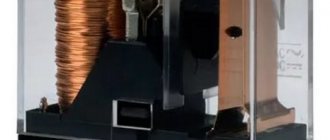
The relay consists of an electric type magnet, an armature and a switch. In this case, the electromagnet is a cable twisted around an inductor with a magnetic rod, and the armature is a special plate that controls the contacts.
As soon as electrical voltage passes through the magnet winding, an electric field is created. A special pusher presses the armature against the core and, thereby, the contacts switch.
Attention. There are two types of relays used on VAZ cars. This is a non-contact relay-regulator and MER (electric). It is the diagram of the last relay that is shown in the picture below.
The non-contact relay or NERR is a fairly new unit that does not require any additional adjustments or regulation. As for the MED, this is an old-style device, the production of which has currently been suspended.
So, the BRN or built-in regulator is a device consisting of a microcircuit, a transistor and a housing with brushes. If the built-in regulator fails, it is replaced with a new one, or an external one is installed.
The external regulator is easy to install if you strictly follow the instructions.
Modernization involves dismantling and disassembling the generating device.
Types of regulator relays
Before you independently repair the voltage regulation device, you must take into account that there are several types of regulators:
- external – increase the maintainability of the generator
- built-in – in the rectifier plate or brush assembly
- regulating by minus - an additional wire appears
- positive regulating – economical connection scheme
- for alternating current generators - there is no function for limiting the voltage on the excitation winding, since it is built into the generator itself
- for DC generators – an additional option for cutting off the battery when the internal combustion engine is not working
- two-level - obsolete, rarely used, adjustment by springs and a small lever
- three-level – supplemented with a special comparison device board and a matching indicator
- multi-level - the circuit has 3 - 5 additional resistors and a tracking system
- transistor - not used in modern cars
- relay – improved feedback
- relay-transistor - universal circuit
- microprocessor - small dimensions, smooth adjustment of the lower/upper threshold of operation
- integral - built into brush holders, therefore they are replaced after the brushes wear out
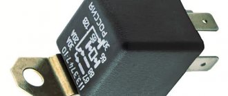
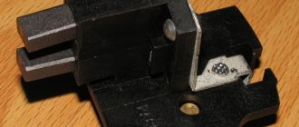
Rice. 7 Remote relay
Rice. 8 Relay built into brush assembly
Rice. 9 Two-level regulator
Rice. 10 Three-level relay
Rice. 11 Transistor-relay regulator
Rice. 12 Microcontroller relay diagram
Rice. 13 Integral regulator
Attention: Without modification of the circuit, the “plus” and “minus” voltage regulators are not interchangeable devices.
DC generator relay
Thus, the connection diagram for the voltage regulator when operating a DC generator is more complicated. Since in the parking mode of the car, when the internal combustion engine is turned off, it is necessary to disconnect the generator from the battery.
This is interesting: Description of the development process and features of the 4a92 engine
During diagnostics, the relay is checked to perform its three functions:
- Battery cut off when the car is parked
- limiting the maximum current at the generator output
- voltage adjustment for field winding
Rice. 14 DC generator voltage regulator
Any malfunction requires repair.
Alternator relay
Unlike the previous case, diagnosing the alternator regulator yourself is a little simpler. The design of the “automotive power station” already includes the function of cutting off power from the battery while parked. All that remains is to check the voltage at the excitation winding and at the output from the generator.
Rice. 15 Relay for alternator
If the car has an alternating current generator, it is impossible to start it by accelerating down a hill. Since there is no residual magnetization on the exciting winding here by default.
Built-in and external regulators
It is important for a car enthusiast to know that they measure and begin to regulate the relay voltage at a specific location where they are installed. Therefore, built-in modifications act directly on the generator, while external modifications “do not know” about its presence in the machine.
For example, if a remote relay is connected to the ignition coil, its work will be aimed at regulating the voltage only in this section of the on-board network. Therefore, before you learn how to test a remote-type relay, you should make sure that it is connected correctly.
Control by “+” and “–”
In principle, the control circuits for “minus” and “plus” differ only in the connection diagram:
- when installing the relay in the “+” gap, one brush is connected to “ground”, the other to the regulator terminal
- if you connect the relay to the “–” gap, then one brush needs to be connected to the “plus”, the other to the regulator
Rice. 16 Scheme for connecting the regulator to the positive wire break
However, in the latter case, another wire will appear, since the voltage relay is an active type device. It requires individual nutrition, so “+” must be supplied separately.
Two-level
At the initial stage, mechanical two-level voltage regulators with a simple operating principle were installed in the machines:
- Electric current passes through the relay
- the resulting magnetic field attracts the lever
- the comparison device is a spring with a given force
- When the voltage increases, the contacts open
- less current flows to the exciting winding
Rice. 17 Mechanical voltage regulator
Mechanical two-level relays were used in VAZ 21099 cars. The main disadvantage was working with increased wear of mechanical elements. Therefore, these devices have been replaced by electronic (contactless) voltage relays:
- voltage divider made of resistors
- The zener diode is the master device
Complex wiring and insufficient voltage control have led to a decrease in demand for these devices.
Three-level
However, two-level regulators, in turn, also gave way to more advanced three-level and multi-level devices:
- the voltage goes from the generator to a special circuit through a divider
- the information is processed, the actual voltage is compared with the minimum and maximum threshold values
- the mismatch signal regulates the current flowing to the exciting winding
Rice. 18 Three-level regulator
Relays with frequency modulation are considered more advanced - they do not have the usual resistances, but the frequency of operation of the electronic key is increased. Control is carried out by logical circuits.