Share
The fuses and relays of the Audi A4 (B5) 1994, 1995, 1996, 1997, 1998, 1999, 2000, 2001 are located in the passenger compartment and engine compartment of the car. Audi A4 (B5) fuses protect electrical devices and circuits from short circuits and voltage surges. Audi A4 (B5) relays are designed to ensure the proper operation of electrical appliances and vehicle equipment.
Please note that all information provided below is for informational purposes only. The exact location of the fuses for this vehicle is indicated on the protective cover or in the repair and operation book that came with the package.
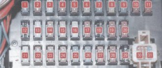
Fuse box No. 1 Audi A4 (B5)
Fuse box No. 1 Audi A4 B5
Fuse box No. 1 in the diagram is located in the car interior on the left side of the instrument panel. To access the fuses, you must open the protective cover using a plastic screwdriver or other auxiliary devices.
| № | Protected circuit | Current in A | ||
| 1 | Heating of windshield washer nozzles | 5A | ||
| 2 | Direction indicators | 10A | ||
| 3 | Headlight washer relay, Lighting: glove box, engine compartment, air conditioning, automatic transmission, Dashboard | 5A | ||
| 4 | License plate light | 5A | ||
| 5 | Instrument panel, Heated seats, automatic transmission display, Mirror switch, Airbag lamp, outside temperature indicator, navigation system, parking lights | 10A | ||
| 6 | Central locking, Reading lamps | 5A | ||
| 7 | ABS system | 10A | ||
| 8 | Telephone | 5A | ||
| 9 | Heated mirrors and door locks | 10A | ||
| 10 | Headlight range control, CD changer | 5A | ||
| 11 | Cruise control automatic transmission | 5A | ||
| 12 | Built-in diagnostics | 10A | ||
| 13 | Brake lights | 10A | ||
| 14 | Interior lighting, reading lights, anti-theft system, passenger visor mirror | 10A | ||
| 15 | Automatic transmission instrument panel, air conditioning, navigation system | 10A | ||
| 16 | ABS system | 5A | ||
| 17 | Heated door locks | 10A | ||
| 18 | Right high beam | 10A | ||
| 19 | Left high beam | 10A | ||
| 20 | Right low beam, electric headlight adjustment | 15A | ||
| 21 | Left low beam, electric headlight adjustment | 15A | ||
| 22 | Right side lights | 5A | ||
| 23 | Left side lights | 5A | ||
| 24 | Windshield wipers, washer pump. Wiper Interrupter Relay | 25A | ||
| 25 | Heater fan, air conditioner | 30A | ||
| 26 | Heated rear window, Heated mirrors, Air recirculation | 30A | ||
| 27 | Rear wiper | 15A | ||
| 28 | Fuel pump | 15A | ||
| 29 | Engine control | 15A | ||
| 30 | Electric sunroof | 20A | ||
| 31 | Reversing lights, cruise control, automatic transmission, diagnostic connector | 15A | ||
| 32 | Engine control | 20A | ||
| 33 | Cigarette lighter | 15A | ||
| 34 | Engine control (ignition/injection) | 15A | ||
| 35 | Trailer electrical equipment | 30A | ||
| 36 | Fog lights | 15A | ||
| 37 | Telephone, Radio | 15A | ||
| 38 | Trunk light/central locking | 15A | ||
| 39 | Emergency lighting | 15A | ||
| 40 | Sound signal | 25A | ||
| 41 | ABS system | 25A | ||
| 42 | Additional air fan | 40A | ||
| 43 | S-contact | 5A | ||
| 44 | Heated seats | 30A | ||
Audi A4 B6 fuses
A large number of fuses provide protection for the vehicle's electronic systems. Each fuse is part of an electrical circuit.
The fuse trips if, for example, as a result of a short circuit (one of the consumers is faulty, the wire is damaged), the current suddenly increases significantly. The fuse link is destroyed, the current is interrupted, and overloading the circuit is prevented.
By the way, this also happens when you connect additional consumers to an electrical circuit that is loaded to the limit.
To ensure that the vehicle is not left without power in the event of an electrical fault, the fuses are distributed over different circuits. The fuel injection system and most electrical components are protected by their own fuses. The connection of the fuses can be determined from the separate circuit diagrams.
Distribution of fuses across circuits
There is a 150 A main fuse located directly on the battery. Most of the fuses for individual consumers and electrical circuits are located in the fuse box on the left of the instrument panel. Under the cover there is a diagram of the placement of fuses, the fuses themselves and plastic tweezers for replacing fuses.
| Fuse table | ||
| Number | Current (A) | Consumer |
| S1 | 10 | Air conditioner control device |
| S2 | 5 | Footwell lights |
| S3 | 5 | Heated spray nozzles |
| S4 | 5 | Radiator fan control device |
| S5 | 10 | Oil level sensor, multifunction switch, telephone settings, tire pressure monitoring, rear seat heating, rear window curtain |
| S6 | 5 | Pressure sensor, air quality sensor |
| S7 | 10 | Backup brake light switch, clutch pedal position sensor, electronic stability control control unit, steering angle sensor, electronic stability control button |
| S8 | 5 | Telephone |
| S9 | 15 | Vacuum pump (brake booster) |
| S10 | 10 | Automatic headlight leveling |
| S11 | 10 | Control unit V30 |
| S12 | 10 | Diagnostic plug socket |
| S13 | 10 | SMLS power supply |
| S14 | 10 | Brake lights |
| S15 | 10 | Combined instrument, navigation |
| S16 | 10 | Not occupied |
| S17 | 10 | Ground clearance, safe parking system, tire pressure monitoring |
| S18 | — | Not occupied |
| S19 | 15 | Fog light, rear fog light |
| S20 | 15 | Low beam left, manual headlight leveling |
| S21 | 15 | Low beam right, manual headlight leveling |
| S22 | 15 | Driver's door |
| S23 | 15 | Front passenger door |
| S24 | 30 | Comfort system control unit |
| S25 | 30 | Heating fan |
| S26 | 30 | Heated rear window |
| S27 | 30 | Trailer control device |
| S28 | 30 | Fuel pump |
| S29 | 20 | Engine control |
| S30 | 20 | Sliding roof |
| S31 | 15 | Diagnostic plug socket, electrochromic rear view mirror, reversing lights |
| S32 | 20 | Engine control |
| S33 | 15 | Cigarette lighter |
| S34 | 15 | Engine control |
| S35 | 30 | Detachable socket - trunk |
| S36 | 30 | Wiper |
| S37 | 20 | ILM control device |
| S38 | 15 | Comfort system control unit, switch off button, active sensor, rear door release button |
| S39 | 20 | Radio |
| S40 | 25 | Sound signal |
| S41 | — | Not occupied |
| S42 | 25 | Control device for electronic vehicle stability control system |
| S43 | 15 | Engine control |
| S44 | 30 | Seat heating |
Of course, there may be some changes and deviations in the distribution of fuses, as it depends on the year of manufacture of the vehicle, the engine and the composition of the equipment. On circuit diagrams, the number 2 is placed before the designation of fuses, starting with fuse S23 (i.e. fuse S39 is designated as S239).
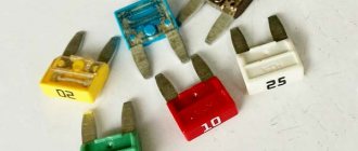
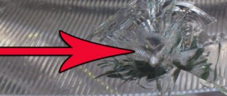
Fuse boxes contain fuses that consist of a clear plastic piece. This part contains two flat pins, which are connected to each other by fusible wire. A blown fuse can be identified by a break in the wire. Often the plastic covering also burns out or breaks off.
- The fuse rating can be determined by the color and inscription on the fuse: Beige 5 amps Brown 7.5 amps Red 10 amps Blue 15 amps Yellow 20 amps White 25 amps
- Green 30 amp
Replacing fuses 1 Before replacing a fuse, turn off the relevant consumer and the ignition. Remove the cover from the fuse box.2 Using plastic tweezers, pull the defective fuse out of the socket.3 Insert a new fuse of the same rated current into the socket. Pay attention to the placement of the fuse.
4 If the fuse immediately blows again, the fuse may be faulty or you may have inserted a fuse with a lower amperage than required. In this case, the cause should be determined immediately. The consumer may be damaged; in the worst case, the wire insulation may catch fire.
Source: https://carpod.ru/predohraniteli-audi-a4-avant-s-2000-g-50.htm
Relay and fuse box No. 2 Audi A4 (B5)
Relay and fuse box No. 2 of the Audi A4 B5 is located inside the car in the steering column on the left side in the direction of travel. To access Relay Block No. 2, it is necessary to dismantle the trim of the steering column space.
| № | Purpose of relays and fuses | ||
| 1 | Auxiliary Ignition Relay | ||
| 2 | Horn relay - two tone | ||
| 3 | Headlight washer pump relay | ||
| 4 | Multifunction relay | ||
| 5 | Washer/wiper control unit | ||
| 6 | Fuel Pump Relay/ Glow Plug Relay | ||
| 7 | Taxi alarm system control module | ||
| 8 | Taxi alarm system control module | ||
| 9 | High beam relay | ||
| 10 | Front fog lamp relay | ||
| 11 | Control unit for exterior rear view mirrors with folding drive | ||
| 12 | Control unit for exterior rear view mirrors with folding drive | ||
| 13 | Starter Disable Switch Relay / Reverse Lamp Relay, with AT / 4-Speed | ||
| 14 | Rear window washer pump relay | ||
| 15 | Free connector | ||
| 16 | A/C compressor clutch relay | ||
| 17 | Lamp warning module | ||
| 18 | Lamp failure warning module | ||
| 19 | Free connector | ||
| F1 | Free connector | ||
| F2 | (20A) Alarm (taxi) | ||
| F3 | (10A) Taximeter | ||
| F4 | (5A) Two-way radio (taxi) | ||
| F5 | (20A) Alarm (taxi) | ||
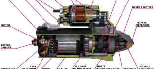
Do-it-yourself starter diagnostics
For the convenience of carrying out work, we place the machine on an inspection hole, preferably a hydraulic lift.
From under the bottom we inspect the electrical wiring, the starter housing, the contact board, terminals, and the battery. In the Audi showroom we carry out troubleshooting of the ignition switch core. We eliminate play, tightness of key rotation, and damage to wires.
At the same time, we measure the charge level at the battery contacts and charge as needed.
If a visual inspection does not reveal a defect, but the trigger mechanism still does not start, then we proceed to dismantling and subsequent disassembly of the mechanism.
Relay block No. 3 Audi A4 (B5)
Relay and fuse box No. 3 Audi A4 (B5) is an additional unit that is present exclusively in cars with diesel engines. Relay block No. 3 is located in the engine compartment of the car depending on the location of the steering wheel. In cars of the European market, the block is located on the left side in the direction of travel of the car. To access the relay, you must unlatch the latches and open the protective cover.
| № | Purpose of relays and fuses | ||
| 1 | Engine Coolant Heater Relay 2 (Diesel) - High Power | ||
| 2 | Engine Coolant Heater Relay 1 (Diesel) - Low Power | ||
| 3 | Engine control relay | ||
| F1 | Free connector | ||
| F2 | (15A) Motor control | ||
| F3 | (15A) Motor control | ||
| F4 | (50A) Engine coolant heater 2 (1.9TDI) | ||
| F5 | (25A) Engine coolant heater (1.9 TDI) | ||
| F6 | (80A) Glow plugs (1.9TDI) | ||
Problems with starter on Audi A4 B5
Faults associated with the electrical power system are classified into electrical and mechanical. The speed of identification of a breakdown and the timing of repairs depend on the professionalism of the technician.
The electric type includes:
- Damage to the insulating layer on conductor products;
- Poor fixation of terminals on the contact board;
- Contacts sticking due to overheating;
- Oxidation of contacts on the end switches;
- Short circuit of armature, winding;
- General malfunction of the trigger mechanism due to moisture entering the housing.
- Third-party mechanical damage to the launcher, body, anchor;
- Wear, deformation of the teeth of the drive shaft, flywheel;
- PU jamming;
- Solenoid relay sticking due to overheating.
Nomenclature numbers of fuses and relays Audi A4 (B5)
| Item name | Item number | ||
| Knife. fuse 10/2×2.8 5A(light brown) | VAG N10 261 501 | ||
| Knife. fuse 10/2×2.8 10A(red) | VAG N10 261 503 | ||
| Knife. fuse 10/2×2.8 15A (blue) | VAG N10 261 507 | ||
| Knife. fuse 19/2×5 15A(blue) | VAG N01 713 112 | ||
| Knife. fuse 19/2×5 20A(yellow) | VAG N01 713 113 | ||
| Knife. fuse 19/2×5 25A (transparent) | VAG N01 713 114 | ||
| Knife. fuse 19/2×5 30A(light green) | VAG N01 713 115 | ||
| Delay relay for vehicles with manual air conditioning control | VAG 8D0 919 578 A | ||
| X-contact relief relay | VAG 8D0 951 253 | ||
| Horn relay | VAG 141 951 253B | ||
| Headlight washer relay | VAG 8L0 955 535 | ||
| Windshield washer/wiper control unit | VAG 191 955 531 | ||
| Fuel pump make contact relay | VAG 4D0 951 253 | ||
| Taxi alarm relay | VAG 443 953 233 | ||
| Glow plug control unit | VAG 8A0 951 253 | ||
| Control unit for headlight/brake light control system | VAG 8D0 919 471 | ||
| Rear wiper control relay | VAG 141 951 253 B | ||
Replacing and installing a starter on an Audi A4 B5
Preparation of tools: heads, ratchet, rags, lubricant, brush repair kit. And also a roller bearing and bushing. If natural light is not enough, we use an additional light source.
We decide on the method of repair: install a new trigger mechanism or restore the current one. From the point of view of economy, it is more profitable to repair the standard starting device. Buying a new one costs 6–8 thousand rubles, and repairs 2–4 thousand rubles. The owner of the technical device has the final say.
- To remove the launcher, we place the Audi on an inspection hole and block the rear row of wheels with wheel chocks. Squeeze the parking brake, remove the terminals from the battery;
- Unscrew the power terminals from the starting device;
- We remove the starting device from the slots and remove it.
We carry out troubleshooting, sort out the control unit, and install it in its original place. We inspect adjacent parts and mechanisms, and if there are signs of wear, replace them with new ones.
Expert advice on care and maintenance
Buy original parts from official sales points. Use the services of certified service stations for diagnostics and prevention.
Do not purchase cheap consumables of dubious origin. Check the catalog numbers with the data contained in the operating instructions.
Do not turn the starter for more than 15 seconds. Wait a pause and try to start the engine again.
The average service life of the starter is 80 – 95 thousand km, scheduled maintenance every 20,000 km.
In case of difficulties in servicing the equipment, additionally read the recommendations in the operating manual, get advice from service station foremen and car dealership managers.
4 cylinder engine
1. Disconnect the negative (-) battery cable.
Caution: Follow the instructions in Section Replacing the battery.
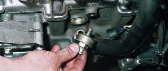
4. Disconnect the B+ terminal wire (2) from the starter.
5. Disconnect the connector of terminal 50 (1).
6. If necessary, remove the insulator on the positive terminal of the starter.
7. Disconnect the cable clamp (4).
8. Petrol engine: Disconnect the holder (3).
9. Remove bolts (1) and (2) and pull the starter forward.
1. Secure the starter with a torque of 45 Nm
(M10 screw) or 65 Nm (M12 screw) at the gearbox.
2. Secure the wire of terminal B+ with a torque of 16 Nm
at the starter.
3. Further installation is carried out in the reverse order of removal.
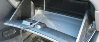
Fuse board on the left side of the dashboard
To access the fuses, open the door and remove the cover. It will look something like this. An example of access is in our video at the end of the article.
Scheme
Description for Audi A4 B8 vehicles up to 2009
| 1 | (5A) Power steering control unit |
| 2 | (5A) Clutch pedal position sensor |
| 3 | (5A) Garage door remote control control unit |
| 4 | (10A) Lane departure warning control unit |
| 5 | (5A) Heater air purity sensor |
| 6 | (5A) Right headlight |
| 7 | (5A) Left headlight |
| 8 | (5A) Onboard power supply control unit |
| 9 | (5A) Dimmable interior rearview mirror |
| 10 | (5A) Gear shift control unit |
| 11 | (5A) Windshield washer nozzle heaters |
| 12 | (5A) Air conditioning system |
| 13 | (5A) Coolant pump motor |
| 14 | (5A) Clutch pedal position sensor |
| 15 | (20A/25A) Fuel pump control unit |
| 16 | (5A) Coolant pump motor |
| 17 | (30A) Onboard power supply control unit |
| 18 | (10A) ABS electronic control unit |
| 19 | (25A) Horn |
| 20 | (30A) Door function control units |
| 21 | (30A) Windshield wiper motor |
| 22 | (25A) ABS electronic control unit |
| 23 | (15A) Door function control units |
| 24 | (5A) Rain and light sensor |
| 25 | — |
| 26 | — |
| 27 | (10A) Power seats |
| 28 | (35A) Power steering control unit |
| 29 | (5A) Antenna signal booster |
| 30 | (35A) Onboard power supply control unit |
| 31 | (20A) Onboard power supply control unit |
| 32 | (30A) Onboard power supply control unit |
| 33 | (20A) Power sunroof control unit |
| 34 | (30A) Onboard power supply control unit |
| 35 | (20A) Sunshade |
| 36 | (5A) Anti-theft system |
Description for Audi A4 B8 vehicles after 2009
| F1 | (5A) Power steering control unit |
| F2 | — |
| F3 | (5A) Garage door remote control control unit |
| F4 | (10A) Lane departure warning control unit |
| F5 | (5A) Heater air purity sensor |
| F6 | (5A) Right headlight |
| F7 | (5A) Left headlight |
| F8 | (5A) on-board power supply control unit |
| F9 | (5A) Distance control unit (cruise control) |
| F10 | (5A) Clutch pedal position sensor, clutch sensor control unit, |
| F11 | (5A) Windshield washer nozzle heaters |
| F12 | (5A) Air conditioning system |
| F13 | (5A) Phone connector |
| F14 | (5A) Hazard warning light button, airbag control unit, seat occupied recognition, |
| F15 | (25A) ABS electronic control unit |
| F16 | (40A) Starter |
| F17 | (5A) Dimmable interior rearview mirror |
| F18 | (5A) Clutch pedal position sensor |
| F19 | (20A/25A) Fuel pump control unit |
| F20 | (10A) Coolant pump motor |
| F21 | (15A/30A) |
| F22 | (10A) ABS electronic control unit |
| F23 | (25A) Horn |
| F24 | (30A) Door function control units |
| F25 | (30A) Windshield wiper motor |
| F26 | (25A) ABS electronic control unit |
| F27 | (15A) Door function control units |
| F28 | (5A) Rain and light sensor. |
| F29 | — |
| F30 | — |
| F31 | (10A) Power seats |
| F32 | (35A) Power steering control unit |
| F33 | — |
| F34 | (35A) |
| F35 | (20A) |
| F36 | (30A) |
| F37 | (20A) Power sunroof control unit |
| F38 | (30A) |
| F39 | (20A) Sunshade |
| F40 | (5A) Anti-theft system |
Audi A4 fuses
The Audi A4 is a highly sought-after sedan car model in almost all regions of the Russian Federation - high build quality, elitism of the model and thoughtful equipment provide the owner with safety and comfort in the cabin, regardless of operating conditions. However, for stable operation of the vehicle, all vehicle systems must be serviced in a timely manner, in particular, monitor the electrical components of the vehicle and replace damaged fuses.
Block in the engine compartment of audi a4 b7
General scheme
This unit is located under the ECM/TCM (battery section). Several decryption options are possible.
Description for gasoline engines
| 1 | Coolant Heater Relay (V6) |
| 2 | Transmission control system relay (Multitronic) |
| 3 | Exhaust air pump relay |
| 4 | Coolant pump motor control unit (AMM/BDV) |
| 5 | Start inhibit switch relay (if installed) |
| F1 | (15A) Engine management system, brake light switch (brake pedal position sensor) |
| F2 | (40A) Exhaust air pump motor |
| F3 | (15A) Automatic transmission control system (6-speed automatic transmission/ Multitronic) |
Description for diesel engines
| 1 | Fuel lift pump relay |
| 2 | Transmission control system relay (Multitronic) |
| 3 | Glow plug relay |
| 4 | Engine control relay |
| 5 | Start inhibit switch relay/reversing light relay(Multitronic) |
| F1 | (15A) Engine management system, brake light switch (brake pedal position sensor) |
| F2 | (60A/80A) Glow plugs |
| F3 | (15A) Automatic transmission control system (6-speed automatic transmission/ Multitronic) |
| F4 | (60A) Glow plugs |
Fuse box in the trunk of an Audi A4 B8
The block is located behind the right side trim. Descriptions of items may differ from those shown.
Scheme
Decoding for cars up to 2010 .
| A | Sedan: Not used |
| B | — |
| C | Sedan: Rear window defroster relay |
| D | — |
| E | Accessory power connector relay |
| 1 | (30A) Trunk lid control unit |
| 2 | — |
| 3 | (30A) Trunk lid control unit |
| 4 | (5A) Plug connector |
| 5 | — |
| 6 | — |
| 7 | — |
| 8 | — |
| 9 | — |
| 10 | — |
| 11 | — |
| 12 | — |
| 13 | (5A) Tire pressure monitoring system control unit |
| 14 | (15A) Trailer electrical control unit |
| 15 | (20A) Trailer electrical control unit |
| 16 | (20A) Trailer electrical control unit |
| 17 | (5A) Electric parking brake control unit |
| 18 | (15A) Suspension control unit |
| 19 | (30A) Electric parking brake control unit |
| 20 | (30A) comfort system |
| 21 | (35A) 4WD electronic control unit |
| 22 | (30A) comfort system |
| 23 | (20A) comfort system |
| 24 | (5A) vehicle location management system |
| 25 | (15A/30A) Accessory power connector |
| 26 | (15A) Seat heating control unit |
| 27 | (7.5A) navigation system/radio |
| 28 | (30A) Audio system |
| 29 | (5A) Multifunction display control unit |
| 30 | (30A) Additional heater control unit |
| 31 | (30A) Electric parking brake control unit |
| 32 | (30A) Seat heater |
| 33 | (30A) Door function control units |
| 34 | (5A) Auxiliary heater remote control receiver |
| 35 | (15A) Door function control units |
| 36 | (5A) Rear view camera control unit |
| 37 | (15A) Accessory power connector |
| 38 | (15A) Accessory power connector |
| 39 | (15A) Accessory power connector |
| 40 | (15A) Cigarette lighter |
| 41 | (5A) Self-parking system control unit |
| 42 | — |
| 43 | (5A) Distance control unit (cruise control) |
| 44 | (15A) Rear window wiper motor |
| 45 | (5A) Electric parking brake control unit |
| 46 | (5A) Lane change assist control unit |
| 47 | (5A) Seat heater |
| 48 | (5A) Hazard warning lights, airbag control unit |
| 49 | — |
| 50 | — |
| 51 | (10A/15A/25A) |
| 52 | (10AL5A) Special automotive equipment |
| 53 | (5A/15A) Special automotive equipment |
| 54 | (10A) Special automotive equipment |
| 55 | (5A/20A) Special automotive equipment |
| 56 | (10A) Special automotive equipment |
| 57 | (10A) Accessory power connector |
| 58 | (10A) Special automotive equipment |
| 59 | (10A) Special automotive equipment |
| 60 | — |
| 61 | (40A) Rear window defroster |
Decoding for cars from 2010 onwards.
| Number | Ampere | Function/component |
| 1 | not used | |
| 2 | not used | |
| 3 | 15A. 25A | Alarm system control unit |
| 4 | 15 A | Alarm system control unit |
| 5 | 5A, 15A | Special signal control panel, Alarm system control unit |
| 6 | BEHIND | Control panel for special signals. Alarm system control unit, Tachograph control unit. Plug connector, 3-pin. Alarm memory |
| 7 | 20 A | Control unit for special vehicles |
| 8 | 10 A | Alarm memory |
| 9 | 10 A | 12V socket |
| 10 | 10 A | Walkie talkie separating relay, walkie talkie relay |
| 11 | 10 A | Walkie talkie separating relay, walkie talkie relay |
| 12 | not used | |
| 13 | 30 A | Luggage compartment lid control unit 2 - |
| 14 | 15 A | Trailer recognition control unit |
| 15 | 20 A | Trailer recognition control unit |
| 16 | 20 A | Trailer recognition control unit |
| 17 | 5 A | AUTO HOLD button |
| 18 | 15 A | Control unit for electronic shock absorber control system |
| 19 | 30 A | Electromechanical parking brake control unit |
| 20 | 30 A | Central control unit for comfort systems |
| 21 | 35 A | All-wheel drive control unit |
| 22 | 30 A | Central control unit for comfort systems |
| 23 | 20 A | Central control unit for comfort systems |
| 24 | 5 A | Vehicle location system interface control unit |
| 25 | 30 A | Luggage compartment lid control unit |
| 26 | 15 A | Right front seat ventilation control unit |
| 27 | 40 A | Radio tape recorder. The phone's transceiver device is a TV tuner. Mobile phone amplifier. Phone holder-. Plug connector, 18-pin |
| 28 | 40 A | Voltage regulator |
| 29 | 30 A | Inverter with socket, 12 V |
| 30 | 30 A | Additional heater control unit |
| 31 | 30 A | Electromechanical parking brake control unit |
| 32 | 30 A | Switch for adjusting the rear left heated seat. Switch with rear right heated seat adjustment |
| 33 | 30 A | Right doors |
| 34 | 5 A | Autonomous heater receiver |
| 35 | 15 A | Right doors |
| 36 | 30 A | Additive dosing system control unit |
| 37 | 15 A | 12V socket |
| 38 | 15 A | 12V socket. Inverter with socket, 12 V - 230 V |
| 39 | 15 A | 12V socket |
| 40 | 15 A | Cigarette lighter |
| 41 | not used | |
| 42 | 5 A | Plug connector, 2-pin, in the back of the driver's seat. Plug connector, 2-pin, in the backrest of the driver's seat |
| 43 | 7.5 A | Parking assist control unit |
| 44 | 15 A | Rear window wiper motor |
| 45 | 5 A | Electromechanical parking brake button |
| 46 | 5 A | Lane change assist control unit 2 |
| 47 | 5 A | Switch with rear left heated seat adjustment |
| 48 | 5 A | Trailer recognition control unit. All-wheel drive system control unit. Voltage regulator. Electromechanical parking brake control unit |
| 49 | not used | |
| 50 | not used | |
| 51 | 20A, 30A | Digital audio system control unit. Radio tape recorder |
| 52 | 7.5A | Information electronics control unit |
| 53 | 5A, 7.5A | Navigation system control unit with CD drive. Radio tape recorder. Telephone transceiver device. TV tuner - Mobile phone amplifier. Phone holder-. Plug connector, 18-pin |
| 54 | 5 A | Rear view camera control unit |
| 55 | 5 A | Mobile phone amplifier |
| 56 | not used | |
| 57 | not used | |
| 58 | not used | |
| 59 | not used | |
| 60 | not used | |
| 61 | 40 A | Rear Window Defogger Relay - Rear Window Defogger |
Fuse number 40 at 15A is responsible for the cigarette lighter.