Hi all! As I wrote a long time ago, I wanted to improve the power supply to the ignition module. This idea came after I accidentally came across an article by user mcsystem, for which I thank him. An additional fuse box was even installed, but another problem arose. My character does not allow me to get involved in the factory wiring; I like it when everything can be returned to stock without major problems. Therefore, I wanted to find the ignition module connectors and make a removable system. The connector that is inserted into the module was found in the store without any problems, but the mating part is more difficult to find. It was decided to rip the connector out of the dead module. But finding a dead module in my city turned out to be problematic. And paying 2 kilo rubles for a new one is stupid because of the connector. That's why the matter stopped.
But the world is not without good people, and exclusive33rus sent me a dead module, for which I thank him very much! At the factory I took two wires with a cross-section of four squares, and real four squares, and not those funny wires that are sold in the store. Well, at the same time, two tips, with holes for 6 and 8 mm, since I still didn’t know which one I would put.
I tore the connector out of the module, measured the required length of wires and began soldering. And here’s a surprise - the metal that connects everything in the module is not soldered with anything! The metal is very shiny, like lead, and brittle to bend like aluminum. I was upset, but there was nothing to do, I had to think further. And then the OBD-II diagnostic KKL cord caught my eye, and I saw that the pins were the same! I disassembled it, found unused pins, heated them with a soldering iron and pulled them out. I pulled out solderless pins of unknown metal from the connector and melted the pins from the cord. I soldered it and decided to fill the soldering area with supermoment and soda. It was with great grief that I found superglue at home, but, as they say, it wasn’t diarrhea—it was scrofula, and there was no soda at home. It seems like such a thing that everyone has had for years and practically never used, but I don’t have it. It was late, the shops were already closed, there was no way to buy anything. And then I remember that on the balcony there is soda ash, which I used to make printed circuit boards using the photoresist method. I try it with superglue - everything is great! I fill the connector, and am faced with the second problem - the wire did not fit into the connector, so about five centimeters to the connector I had to slightly reduce the cross-section, from four squares it dropped to about 2.5, but I thoroughly tinned everything, so the losses will be minimal. I put everything in the corrugation and leave the wiring until daylight; it’s not very convenient to install in the dark.
As you can see, there is a relay in the circuit. Those who understand electrics, I think, understood immediately, but for the rest I’ll explain what I can do. So, there are four wires going to the module, two signal wires, through which the ECU gives the command to give a spark to the cylinders (1-4 and 2-3, respectively), and two 12 volt power supply. So the signal signals go directly from connector to connector, but the module’s power now goes to the relay, through which +12 volts goes directly from the battery with a thick wire.
Pinout and diagram of the VAZ ignition coil
Pinout of ignition coil modules for various car models of the VAZ family:
Ignition VAZ 2101
1 – generator; 2 – ignition switch; 3 – ignition distributor; 4 – breaker cam; 5 – spark plugs; 6 – ignition coil; 7 – battery.
Ignition VAZ 2106
1 – ignition switch; 2 – fuse and relay block; 3 – EPHH control unit; 4 – generator; 5 – solenoid valve; 6 – microswitch; 7 – spark plugs; 8 – ignition distributor; 9 – ignition coil; 10 – battery.
Ignition VAZ 2108, 2109
Ignition VAZ 2110
Ignition VAZ 2111
Ignition VAZ 2112
Ignition VAZ 2114
Diagram of a non-contact ignition system: 1 – non-contact sensor; 2 – ignition distributor sensor; 3 – spark plugs; 4 – switch; 5 – ignition coil; 6 – mounting block; 7 – ignition relay; 8 – ignition switch.
Connection diagram
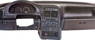
The ignition module is part of the space under the hood, it’s easier to find it by the position of the high voltages, they go from the spark plugs straight to it.
Ignition coil diagram:
VAZ 2114 ignition coil diagram
This diagram is good to follow when you have to replace the ignition coil of a VAZ 2114. In principle, everything is transparent: from contacts with the controller (ECU) to high-voltage wires. The name of the circuit is often common under the name ignition coil pinout: the pinout is a visual representation of the functionality of the device's contacts, which are numbered according to their purpose.
It can be connected in two different ways: when the ignition system coil is removed and when it is directly in its place in the car engine.
If you are holding the module in front of you:
- Let us recall the diagram: the first and fourth contacts are on one winding, the second and third – on the other (they are numbered in the diagram!)
- Then, the lower explosive contact (left) goes to the first cylinder
- On the second - upper explosive contact (left)
- The third cylinder goes to the upper explosive contact (right)
- On the fourth – lower explosive contact (right)
If the module is plugged into the engine, then pinouting the explosive contacts will be more difficult, because the device stands at an angle (as if in a diamond):
- We throw the central lower contact onto the first cylinder
- On the second - left contact
- We put the upper contact on the third cylinder
- On the fourth - right contact
Of course, the first installation option is more convenient, especially since the explosive wires require increased care in the nature of the connection (mixed up and won’t start, in the worst case, the entire engine system is ruined). Speaking to the point, it is clear that the connection diagram for the VAZ 2114 ignition module is not complicated.
By the way, buying an ignition coil is not a cheap pleasure; the price of an ignition module for a VAZ 2114 ranges from seven hundred to a thousand rubles, depending on the location of your city on the map of our country (for more information about how much an ignition module for a VAZ 2114 costs, you can find out by calling a disassembly service or a spare parts store, the running part is almost always in stock).
How to check the ignition coil of a VAZ
If the ignition coil is faulty, the engine will not start. A characteristic sign of a faulty coil is its increased temperature when the ignition is turned off. This is easy to determine by touch.
Signs of a faulty ignition module may include the following:
- hesitant engine starting or failure to start;
- failures during sudden changes in speed;
- high fuel consumption;
- two cylinders do not work, the engine is feverish;
- lack of dynamics;
- a sharp drop in power;
- drop in power and thrust after warming up.
These symptoms may not only be caused by the ignition module. To determine the malfunction, it is enough to spend a few minutes diagnosing spark plugs, high-voltage wires and caps. This will eliminate the remaining elements of the ignition system and make sure that it is the ignition module that is faulty.
What's the difference between contactors and starters?
Both contactors and starters are designed to close/open contacts in electrical circuits, usually power ones. Both devices are assembled on the basis of an electromagnet and can operate in DC and AC circuits of different powers - from 10 V to 440 V DC and up to 600 V AC. Have:
- a certain number of working (power) contacts through which voltage is supplied to the connected load;
- a number of auxiliary contacts - for organizing signal circuits.
So what's the difference? What is the difference between contactors and starters? First of all, they differ in the degree of protection. Contactors have powerful arc extinguishing chambers. This leads to two other differences: due to the presence of arc arresters, contactors are large in size and weight, and are also used in circuits with high currents. For low currents - up to 10 A - only starters are produced. By the way, they are not produced for high currents.
There is one more design feature: the starters are produced in a plastic case, with only the contact pads exposed outside. Contactors, in most cases, do not have a housing, therefore they must be installed in protective housings or boxes that will protect against accidental contact with live parts, as well as from rain and dust.
In addition, there is some difference in purpose. The starters are designed to start asynchronous three-phase motors. Therefore, they have three pairs of power contacts - for connecting three phases, and one auxiliary one, through which power continues to flow to operate the engine after the “start” button is released. But since a similar operating algorithm is suitable for many devices, a wide variety of devices are connected through them - lighting circuits, various devices and devices.
Apparently because the “filling” and functions of both devices are almost the same, in many price lists the starters are called “small contactors”.
Connecting and replacing VAZ short circuit
The procedure for removing and installing the ignition coil on old VAZ models:
- First, disconnect the central high-voltage wire leading to the distributor (ignition distributor).
- Disconnect all power wires from the coil contacts. Since they are fastened with nuts, you will need an 8 wrench for this.
- If you don’t know which wires to connect to which connector later, it’s better to immediately remember or mark them somehow, so that later during installation you can connect them correctly.
- Unscrew the coil housing. It is attached to a clamp (clamp), which is pressed to the car body with two nuts.
- After the work has been done, you can remove the ignition coil and replace it if necessary.
For new type VAZ cars:
- We remove the “minus terminal” from the battery.
- Remove the top protective cover of the engine. If the engine volume is 1.5 liters, then this part is missing and this step is skipped.
- We remove the high-voltage wires from the coil.
- Now, using a 13mm wrench, unscrew the two fasteners.
- Using a 17mm wrench, loosen one bolt securing the coil.
- We take out the module.
- Use a hexagon to unscrew the coil from the holder.
- Assembly is carried out in reverse order.
Particular attention should be paid to the connection, since high-voltage wires must be located in the strict order provided for by the design. If this is not done, the car will stall or the engine may not start at all.
Replacing the ignition coil on a VAZ is quite simple. Even a novice motorist can do this in his garage, and if everything seems too complicated, contact a car service center. Particular attention should be paid to the choice of product, since this will determine how well the engine and ignition system will work.
Checking the performance of the coil
No. Check Description 1 External inspection Remove the coils from the cylinders. First, let's inspect the rubber part.
There should be no breaks or cracks on it, and if there are any, it means that the coil has served its purpose and needs to be replaced. Then we look inside, see what condition the internal spiral is in, its position. 2 Checking the primary winding of the coils with a multitester (checking Priora coils with a multitester) Before connecting the device to the coil, you need to check its internal resistance in order to take into account possible errors. We connect the tester to the primary winding. If the device shows no more than 0.5 Ohm, taking into account the measurement error, then everything is fine with this coil. 3 Checking the secondary winding of the coils with a multitester Switch the tester to 2000 kOhm Connect the probes to different parts of the coil observing polarity: the red contact is to the spring under the rubber cap, and the black one is connected to the middle contact of the connector
A working Priora ignition coil shows a secondary winding resistance of 342 kOhm. A faulty tester will show infinity.
You need to remove the coil from its place by disconnecting the negative terminal of the Priora battery. Decorative plastic is removed from the motor. Then you need to press out the plastic clamp and disconnect the coil from the wiring, after which the fastening bolt is unscrewed with a 10mm wrench and the device is removed from the spark plug well.
Currently, there is simply no trust in standard Priora coils. Some immediately replace them with foreign-made devices, with Bosch products being especially popular. Since the designers have not eradicated this hereditary problem in the Priora model, the owners themselves will have to correct it, investing not so small sums, because Bosch sometimes asks for no less than 1,500 rubles apiece.
Problems with coils can lead to sudden jerks in engine operation, speed surges, and cylinder failures. Therefore, if you have such symptoms, it is better to use the above information and replace the suspicious part before it completely fails. It also happens that the coil has not yet broken, but is already malfunctioning. This does not necessarily mean that a replacement is needed; some repairs will do, or rather cleaning of water condensation and dirt.
Experienced drivers have verified that after a couple of hours of painstakingly cleaning the coils, the motor stops tripping and works like new. It turns out that it did not burn out, but simply passed current in places. Such a nuisance can be eliminated even on the road. It is enough to remove condensation and wipe important parts with gasoline to remove dirt. If you attach heat shrink to the coil, there will never be problems with interruptions again, and Priora will not spoil the mood of its owner.
Sometimes coils fail when the spark plug gap is incorrect. Checking the performance of the coil on a Priora car can be easily done by turning the crankshaft. To do this, you need to relieve the pressure in the fuel system and remove the fuel pump fuse. Then we remove the coil, insert a spark plug into its rubber tip, and connect the wires to the coil itself.
After this, we carefully place the experimental spark plug on the cylinder block, ensuring contact between the spark plug and the mass. Do not touch the spark plug coil with your hands to avoid getting an electric shock. Now you need to turn the crankshaft. An assistant does this while you look carefully at the candle. A spark should appear between its electrodes when the starter is turned on and the shaft is turned. This is an indicator of her work.
You can check the coil power circuit. You need to take the multitester mentioned above and connect its probes to its terminals. If you turn on the ignition at this moment, the tester should show a voltage equal to that at the battery terminals. Otherwise, it is necessary to check the circuits for opens and shorts. If the power and control circuits are working properly, but when checking there is no spark on the working spark plug inserted into the tip, then the coil is faulty and will have to be replaced.
VAZ models 8 and 16 valves
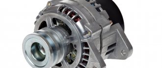
Despite the similarity in engine design, the ignition system of the 1.5-liter injection 16-valve engine differs from the 1.6 16-valve engine. The 1.6 liter engine uses an electronic contactless ignition system with individual coils on each spark plug. Therefore, there was no need for an ignition module. Such a system is more reliable and cheaper to operate, since if one coil fails, there is no need to replace the entire module.
The 16-valve 1.5-liter VAZ 2112 injection engine used the same non-contact ignition system as the 8-valve engine, but a different ignition module was installed. Its catalog number is 2112-3705010. The design of the module remains the same - two ignition coils (for cylinders 1-4 and 2-3) plus switch keys in a single block. The spark is supplied to the cylinders in pairs using the idle spark method. This means that sparking occurs in two cylinders simultaneously - in one on the compression stroke (working spark), in the second on the exhaust stroke (idle spark).
We disassemble the design of the ignition module of a modern injector
As an example, consider a similar device used on injection VAZ cars. The module operates according to the good old principle: 12 volt power is supplied to the input, and a high voltage is generated at the output contacts for sparking.
The control is electronic, but the operating principles differ from a simple distributorless ignition system:
- All components are located in one housing. On the one hand, this is convenient - fewer wires and contacts - lower probability of breakdown. On the other hand, if the ignition module burns out, it must be repaired; simply replacing the failed element will not work.
- The device is compact and can be conveniently placed in the engine compartment.
- The ignition module is powered at low voltage, which increases the reliability of the device.
- The cost of the finished device is low.
- This ignition module has two coils. This contributes to the survivability of the device - each transformer is loaded twice as much.
The secret of the module’s operation is as follows: it uses not four, but two coils for 4 cylinders. Masters of the old school call this device a two-spark bobbin. Alternating connection of each coil produces two sparks: working and idle. Due to proper distribution among the spark plugs, the idle spark is ignited at the moment when there is no air-fuel mixture in the corresponding cylinder.
The signal for sparking is given by the switch (acting as an electronic distributor). Before checking the ignition module, you need to make sure that control pulses are coming to the contact blocks from the switch.
This block is responsible for the so-called ignition advance, that is, it generates a signal at the right moment. The control pulse about the position of the crankshaft is issued by the Hall sensor, which also synchronizes the operation of the entire system.
Video on repairing KZ VAZ
Often, when the ignition module breaks down, the car owner immediately runs to the store and buys a new one. But, for the VAZ-2112 there is an alternative method - repair. Of course, without proper knowledge in auto electrics, it will be difficult to understand all the circuits and communications. This article will tell you in the most accessible way how to repair the ignition module with your own hands.
Tip repair
High-quality coils for a Priora car can withstand from 50 to 100,000 km. To increase the life of the coils, you need to prevent engine oil from coming into contact with them.
A cracked ignition coil tip is a common problem. However, you can return the coil to working condition by making repairs on your own, provided that the coil itself has not burned out. This will require a degreasing wipe, a silicone ignition coil O-ring (new), a new tip and silicone sealant. The whole procedure will take a couple of minutes.
Remove the old tip. If the o-ring is damaged, remove it too. To install the tip, its skirt is turned inside out. We take the previously prepared sealant and apply it to the lower part of the tip with a cotton swab. We do this slowly so that there is no excess sealant left around the edges. We put the tip on until it stops.
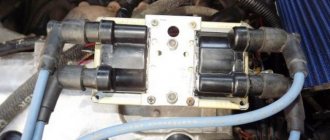
Module design
Before you begin repairing the ignition module, it is worth understanding what it consists of. So, let's look at the design of this element:
- Two ignition coils that generate a high-voltage pulse.
- Dual channel switch.
If there are problems with the operation of the ignition module, there are reasons for this. It is worth warning that in the event of a malfunction, the “Check Engine” warning light will not light up: engine stops, loss of spark, interruptions in the operation of the power unit, etc.
For diagnostics and repairs, basic knowledge is required not only in conventional electrics, but also in the principles of auto electrics. Also, for a successful process you will need skills in working with a digital multimeter.
Repair process
Often, the high-voltage pulse disappears in cylinders 2 and 3 . So, to begin repairing the ignition module, of course, you will need to dismantle it. To do this, disconnect the high-voltage wires and unscrew the assembly itself from the fastenings. When the preparatory operations are completed, you can proceed directly to the repair process:
- We tear off the aluminum plate.
Use a screwdriver to open the aluminum plate
Scheme of soldering wires and arrangement of elements on the boards
Diagram of the assembled ignition module
Completely assembled ignition module
Video about repairing the ignition module on a VAZ-2112
The video material will tell you about repairing the ignition module, as well as how to remove it from the car.
Diagram of the correct connection of wires to the ignition module
If, after checking the wires, you are convinced that they are all tightly connected to the spark plugs, let’s check that the wires themselves are connected correctly. Of course, if no one has climbed into the engine before you, then there is no point in checking. If there was traction and it disappeared, the reason could be both in the coil and in the wires themselves - they could be pierced. But in any case, let's check that the connection is correct. The ignition module shows the numbering of the cylinders to which the wires fit.
- 1 cylinder – central lower outlet
- Cylinder 2 – left output
- Cylinder 3 – top outlet
- 4 cylinder – right output
The diagram is shown for a coil installed on a vehicle.
If after checking no problems are identified, you should consider replacing the coil or wires. It is advisable to change both.
The cost of PVN, depending on the manufacturer, ranges from 300 to 600 rubles per set. The most popular manufacturers:
The cost of an ignition coil is from 1300 to 2500 rubles. Modules from the following companies can be found in stores:
When choosing a module, you should pay attention not only to the manufacturer, but also to the coil itself; it comes in old and new designs. Therefore, it is better to dismantle yours and bring it to the store.
Checking the Ministry of Health with your own hands
There are several options for checking the device yourself at home; let’s look at the simplest one.
To carry out independent diagnostics, you need to know what the wires connected to the module are responsible for:
- red-blue - provides 12-volt power to the device;
- the brown wire is ground, usually connected to the car body;
- white-blue - connects to the spark plugs of the first and fourth cylinders;
- the red-gray wire connects to the spark plugs of the second and third cylinders.
Scheme of the VAZ module
First, you need to check with your own hands that all pulses are sent to the ignition device 2112:
- First of all, you need to turn off the ignition and disconnect the connector.
- Next, the key in the lock must be moved to position I.
- Now you will need a dial voltmeter; it must be connected to the negative terminal of the battery.
- With the second probe, that is, the plus one, you need to find the 12-volt contact on the connector.
- When connected to the control contact, the arrow on the tester will show almost 0.
- If the starter unit starts working, the parameters may increase, but they will not exceed 0.7 volts. Please note that the voltage level at both control contacts must be identical.
There is another test option - you can diagnose the functionality of the module using a pointer ohmmeter. In this case, we mean a pointer tester, not a digital one. First you need to connect the probes of the device to pins 1 and 4 of the module, and after that to pins 2 and 3. Ultimately, the diagnostics should show the same result.
Please note that depending on the manufacturer, these parameters may differ:
- for devices manufactured by ATE-2 with number 3705010-02, this parameter should be about 5-6 kOhm;
- for SOATE modules with number 3705010-12, diagnostics should show 12 kOhm.
If the obtained indicators differ from those described above, then the module must be replaced. Please note that the inductance of the coils installed inside the MZ is quite high, therefore, connecting an ohmmeter, a spark may slip. Therefore, when diagnosing, we strongly do not recommend touching the probe leads at the same time (the author of the video is Avtoelektika HF).
Instructions for replacing the module
If checking the VAZ 2112 ignition module showed that the device needs to be replaced, then you can change the ignition module yourself.
The replacement process looks like this:
- Initially, you should turn off the power to the on-board network; to do this, you just need to disconnect the negative terminal from the battery. Many car enthusiasts neglect this step, although in fact it is very important. If you do not disconnect the battery, a short circuit may occur as a result of moisture or other external influences during repairs. And if this happens, then there is a chance that you will have to completely change the wiring in the car. So, to reset the battery terminal, you just need to unscrew the bolt that secures it with a wrench.
- Having done this, you will need to disconnect all high-voltage wires connected to it from the module. At the same time, you need to remember their location so that during installation you do not accidentally confuse them, which, again, can be fraught with danger for the entire system as a whole.
- After completing these steps, you will need to disconnect the connector with wires from the device itself. To do this, grab the block with your hand and press the latch with which it is attached - the fastener is located at the bottom, you can feel it with your hand. Having done this, you will need to remove the block and put it aside so that it does not interfere with you in the future.
- So, now you have two options - remove the device together with the mount or remove it separately. The first option is usually relevant in cases where, in addition to replacing the MZ, you need to perform other repair actions, for example, to get to the antifreeze drain hole of their cylinder block. Of course, it will be more convenient to dismantle the module separately, but then access to other parts and elements will be blocked. To dismantle you will need to unscrew the nuts with your own hands that secure the device to the bracket. Depending on the car, the nuts can be different; for example, they can be made in the form of hexagonal studs. If so, you will need a hex wrench to unscrew them. In any case, after unscrewing the nuts, it is necessary to dismantle the module from the seat.
- The procedure for installing a new module is carried out in a similar way, only in reverse order. When connecting with your own hands, be careful and be sure to correctly connect all the wires that connect to the module from the spark plugs . If at this stage you mix up the cylinder numbers on the high-voltage cables, the power unit may not work correctly or may not start at all.
Photo gallery “Replacing the MZ with your own hands”
Price issue
The cost of the device directly depends on the manufacturer. For example, the price for a new MZ from the manufacturer SOATE is about 1,700 rubles. A module from the manufacturer BOSCH will cost around 2 thousand rubles, and from General Motors - about 5 thousand rubles.
Spark plug
The VAZ-2101 used Soviet spark plugs of the A17DV brand, but now, when the market is filled with high-quality foreign-made brands, you can easily choose spark plugs with much better characteristics, the main thing is not to fall for a Chinese counterfeit.
Design features of candles
The length of the threaded part of the spark plug is 19 mm, with a pitch of 1.25. The hexagonal part (for the spark plug wrench) is made with a size of 20.8 mm.
The permissible gap between the spark plug electrodes is checked with a probe. According to the book, with a contact system, the gap of the VAZ 2101 spark plug should correspond to 0.5 - 0.6 mm.
Distributor
On VAZ 2101 models until 1980, a distributor (distributor) of the R-125B model was used. Its peculiarity was the absence of a vacuum regulator; there was only a mechanical type octane corrector, which made it possible to slightly change the ignition timing (IZ).
Beginning in 1986, together with the installation of the Ozone carburetor, a distributor equipped with an OZ vacuum regulator (model 30.3706), the design of which is described below, began to be installed on VAZ engines.
Model 30.3706 consists of a distributor, a breaker and two regulators - centrifugal and vacuum.
The distributor ensures the distribution of coil pulses among the spark plugs in accordance with the operating order of the power plant.
It consists of a rotating rotor and fixed segments located in a plastic cover. There are two contacts on the rotor - central and side, with an interference suppression resistor attached between them. A graphite electrode is pressed from above to the central contact; for better contact, pressing is carried out by a spring.
The distributor works like this:
the voltage from the secondary winding is supplied to the rotor, then through a spark gap of approximately 0.5 mm it enters one of the segments of the distributor cover, then through high-voltage wires to the spark plug, which ensures the appearance of a spark.
The breaker ensures that the electrical circuit opens at the right time. Its design includes a cam washer with edges and a contact post. The edges of the cam washer are specially shaped to ensure quick opening of the contacts, smooth closing of the contacts and absence of rattling.
The rotating cam alternately closes and opens the contacts, thereby interrupting the voltage supply to the primary circuit of the coil.
The breaker and distributor must work synchronously with the crank mechanism. To ensure synchronization, the cam washer and rotor are located on the same shaft, and are driven by the camshaft.
Centrifugal regulator – provides a change in the angle of rotation in accordance with the rotation of the knees. shaft
A plate with movable weights is welded to the top of the cam bushing. With increasing knee speed. shaft, the weights move apart due to centrifugal force, turning the plate together with the cam in the direction of shaft rotation. This ensures earlier opening of the contacts (increasing the angle of contact).
Vacuum regulator – adjusts the OP angle depending on the load of the power unit and the position of the throttle valve.
It is attached to the distributor and includes a housing and a cover. The body is divided by a plastic membrane into two cavities, one of the cavities is connected to the throttle space in the carburetor, and the second to the atmosphere. The membrane can act on the breaker through traction.
As the load decreases, the filling of the cylinders with the combustible mixture and the pressure during ignition decreases, and this requires an increase in the angle of ignition. To do this, the membrane bends (under the influence of a pressure difference) and rotates the breaker to the desired angle.